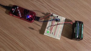
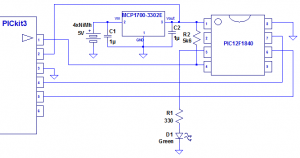
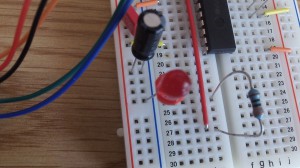
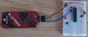
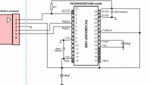
A much better way to blink the LED is to use a timer, and rely on the timer generating an interrupt on the timer expiry. This is more accurate, and also doesn’t hog the CPU. Using the same setup as before (using the PIC12F1840), we change the code as follows:
#include <xc.h>
#include <stdio.h>
#include <stdlib.h>

// CONFIG1
#pragma config FOSC = INTOSC // Oscillator Selection (INTOSC oscillator: I/O function on CLKIN pin)
#pragma config WDTE = OFF // Watchdog Timer Enable (WDT disabled)
#pragma config PWRTE = OFF // Power-up Timer Enable (PWRT disabled)
#pragma config MCLRE = ON // MCLR Pin Function Select (MCLR/VPP pin function is MCLR)
#pragma config CP = OFF // Flash Program Memory Code Protection (Program memory code protection is disabled)
#pragma config CPD = OFF // Data Memory Code Protection (Data memory code protection is disabled)
#pragma config BOREN = ON // Brown-out Reset Enable (Brown-out Reset enabled)
#pragma config CLKOUTEN = OFF // Clock Out Enable (CLKOUT function is disabled. I/O or oscillator function on the CLKOUT pin)
#pragma config IESO = ON // Internal/External Switchover (Internal/External Switchover mode is enabled)
#pragma config FCMEN = ON // Fail-Safe Clock Monitor Enable (Fail-Safe Clock Monitor is enabled)

// CONFIG2
#pragma config WRT = OFF // Flash Memory Self-Write Protection (Write protection off)
#pragma config PLLEN = ON // PLL Enable (4x PLL enabled)
#pragma config STVREN = ON // Stack Overflow/Underflow Reset Enable (Stack Overflow or Underflow will cause a Reset)
#pragma config BORV = LO // Brown-out Reset Voltage Selection (Brown-out Reset Voltage (Vbor), low trip point selected.)
#pragma config LVP = OFF // Low-Voltage Programming Enable (Low-voltage programming enabled)

int counter = 0;

int main(int argc, char** argv)
{
  TRISA = 0xEF; // Set RA4 pin as output

  OPTION_REG = 0xC7; //Set prescaler to 256
  TMR0 = 0xFF; //Timer0 module register
  TMR0IE = 1;
  ei(); //Enable all configured interrupts

  while (1); //Loop forever

  return (EXIT_SUCCESS);
}

void interrupt Timer0_ISR(void)
{
  counter++;
  RA4 = counter & 1;  //Toggle the LED
  TMR0IF = 0;         //Clear the timer interrupt flag
}
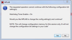
Notice that we have also included a configuration section. Apart from anything else, this will get rid of the annoying messages about the low power programming and watchdog (the watchdog is a very useful feature, but that will have to wait for another day). There is an easy way to generate the configuration, which is to select Configuration Bits from the Window / PIC Memory Views menu item. From there you can change the options and the press the Generate Source Code to Output button.

