HAM Radio and Maker World Exhibition at Friedrichshafen in Germany 2014

http://www.hamradio-friedrichshafen.com/ham-en/index.php

Main Entrance

Friedrichshafen HAM Radio Exhibition

This was my first ever visit to the HAM Radio and Maker World Exhibition at Friedrichshafen (I think was their 39th year). They were joined this year for the first time by the Maker World exhibition which was also very interesting.


Hall A4

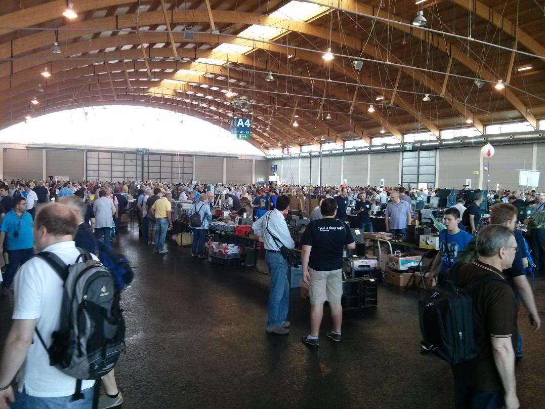
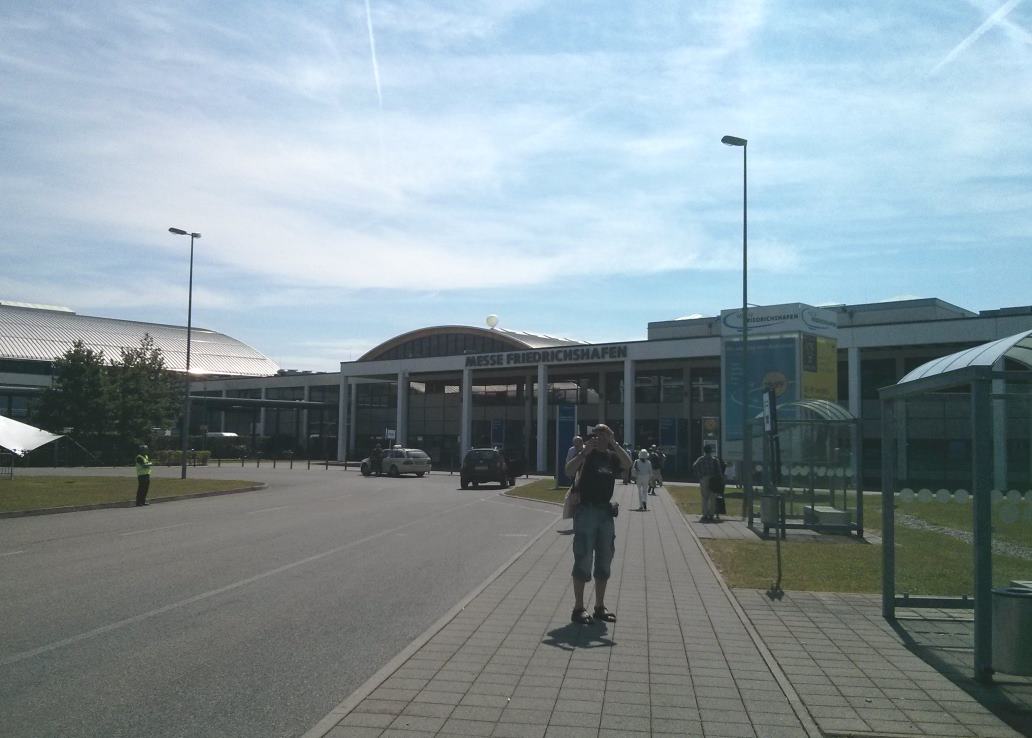
You can’t really appreciate the size of the hall from this picture!

In case you don’t know, this is the biggest amateur radio exhibition in the world – there were three very large halls for the HAM radio, and one for the Maker World exhibition.


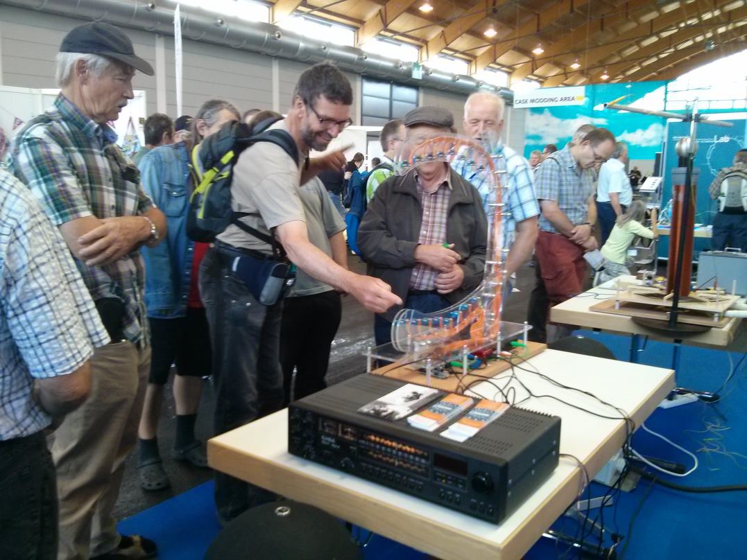
Here’s a few pictures of the HAM radio exhibition. This doesn’t really do it justice, but there are plenty of other people that have covered this in previous years (e.g. try searching for “ham radio friedrichshafen” in google images).

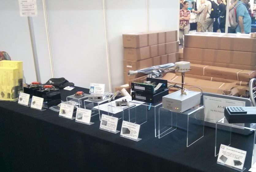
Every radio manufacturer had a stand in the main hall, this is a couple of the stands:

FR_Yaesu

.FR_A1_1

There was also a lot of second hand equipment and components available in the flea market:

FR_Fleamarket1 FR_Fleamarket2 FR_Fleamarket3

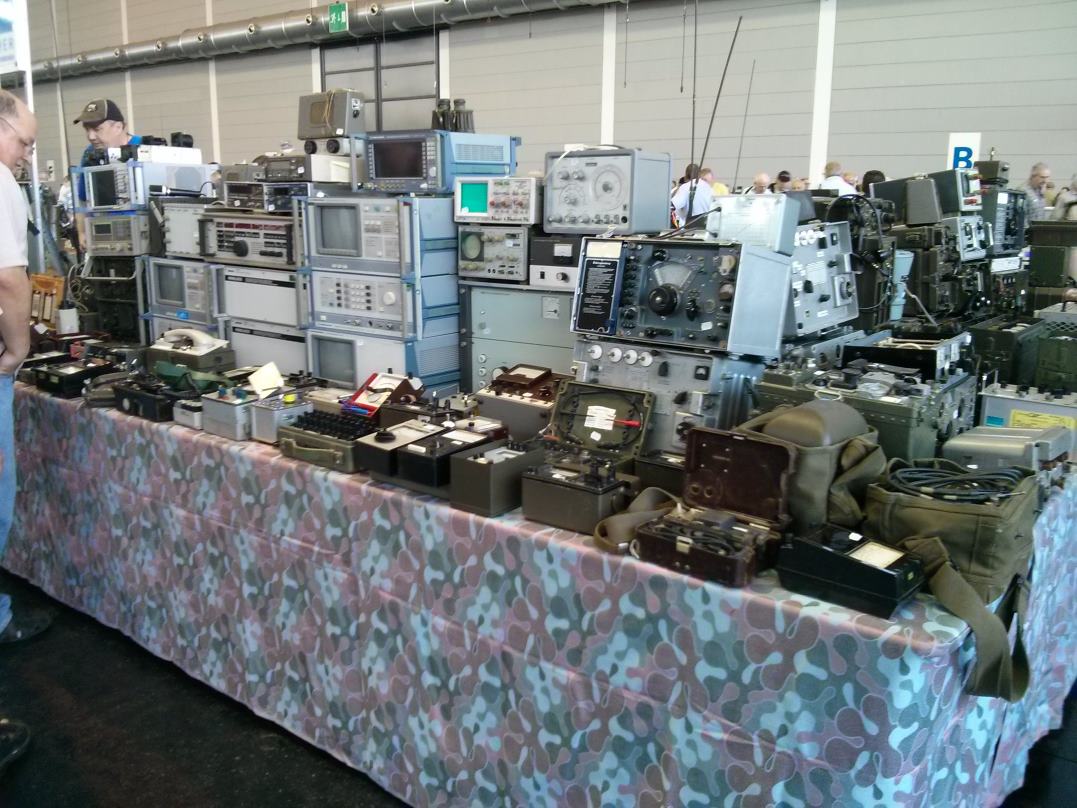
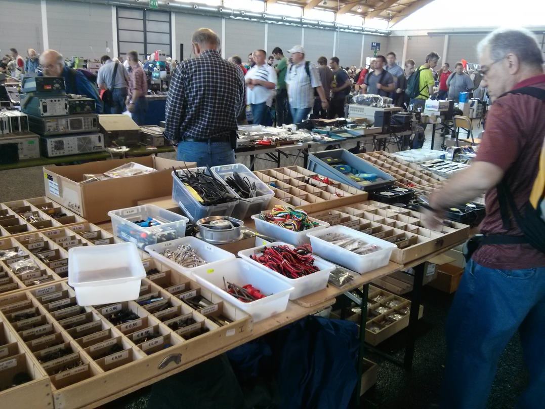
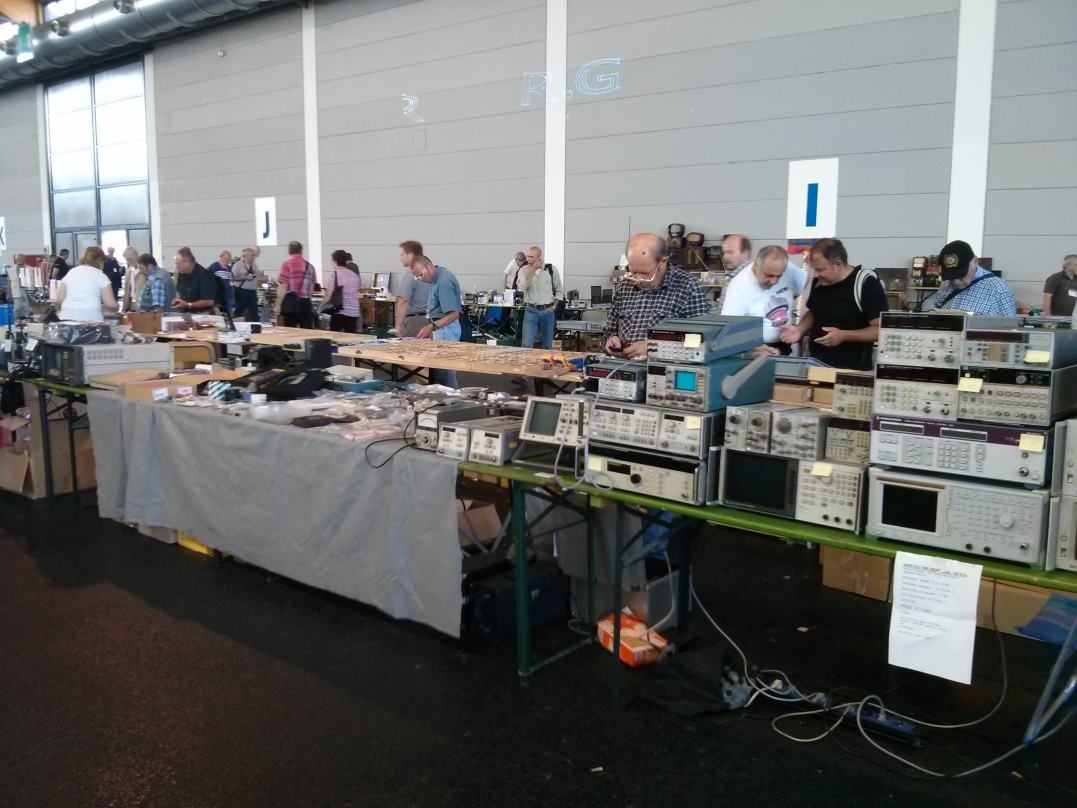
This included some very old and ex-military equipment.


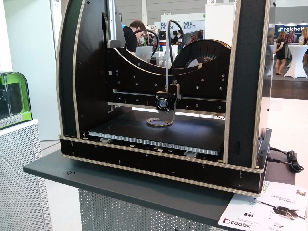
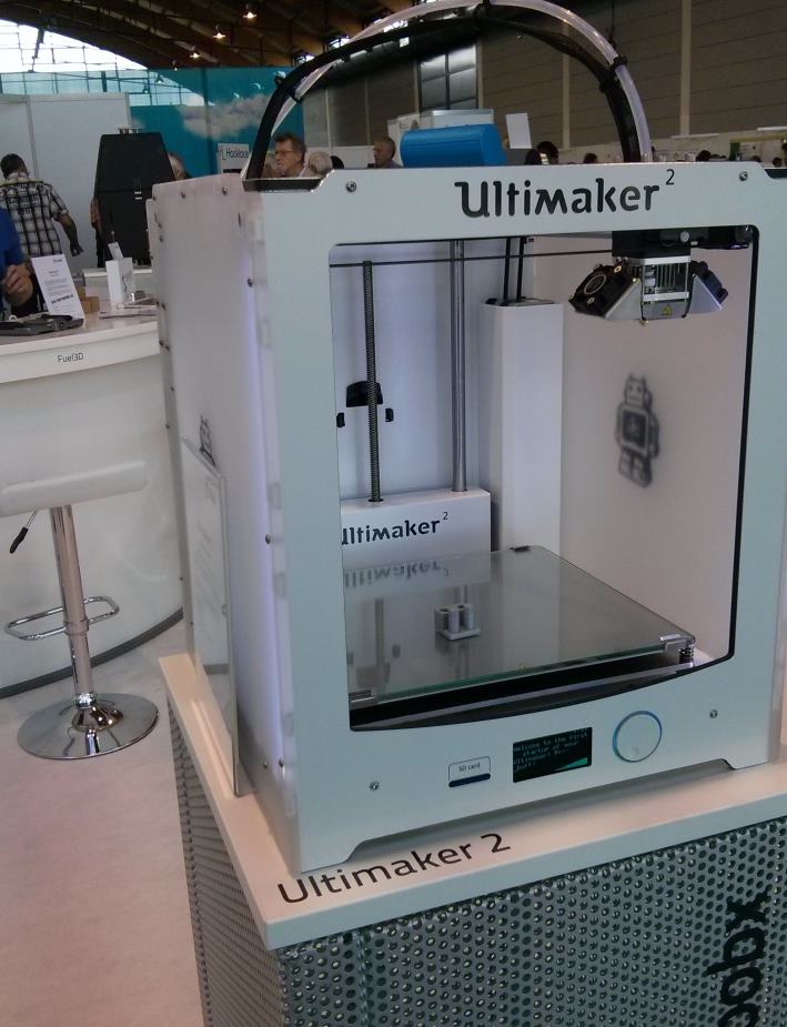
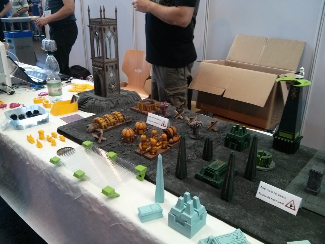
The Maker World exhibition was in hall A5, and seemed to be quite heavily dominated by 3D printers:

FR_3DPrinter2 FR_3DPrinter3 FR_3DPrinter4 FR_3DPrinter1

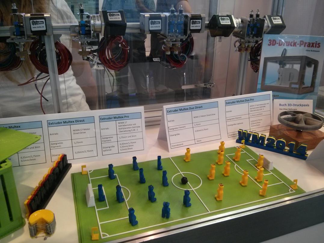
And objects that could be made with these printers:

FR_3DPrintFigures2 FR_3DPrintFigures1

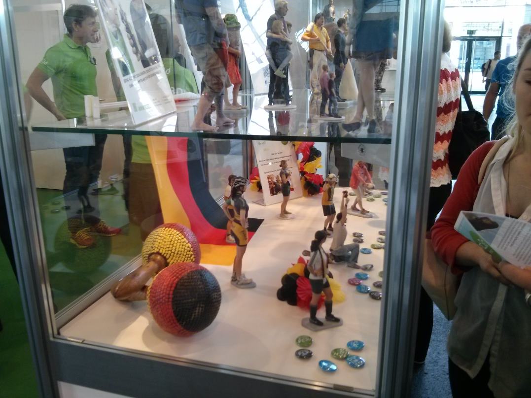
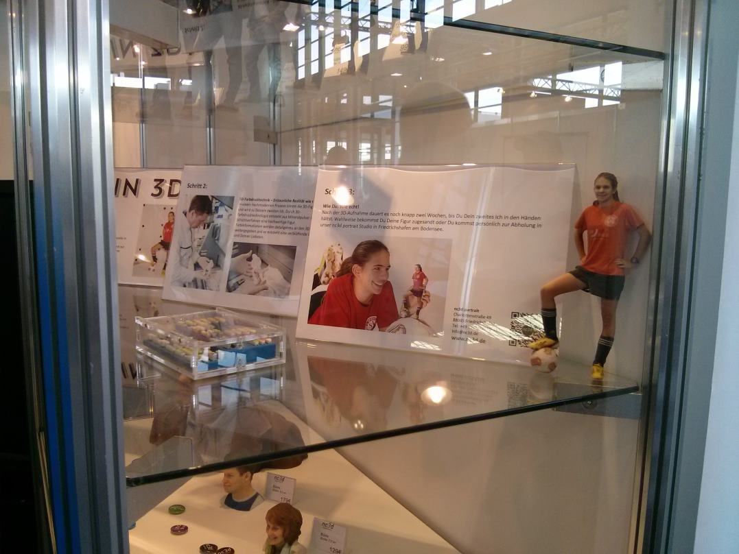
There was also a company that would make a mini model of you (I think like they did on the TV show the Big Bang Theory):

FR_3DPrintPerson2 FR_3DPrintPerson

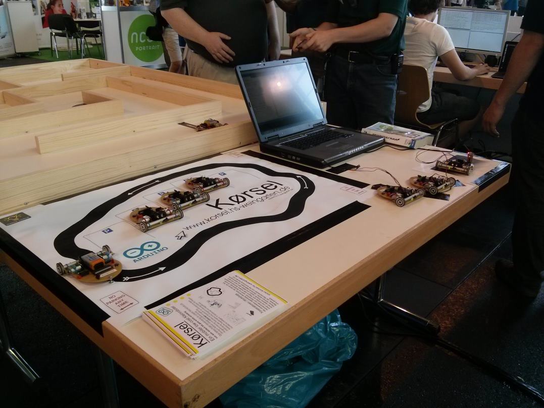
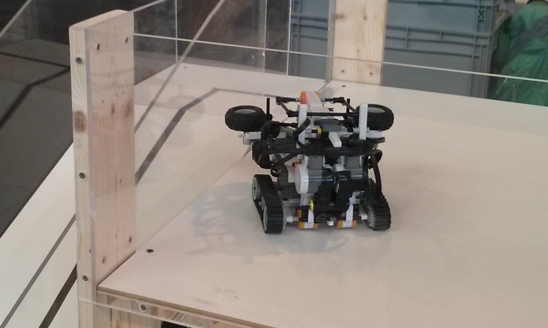
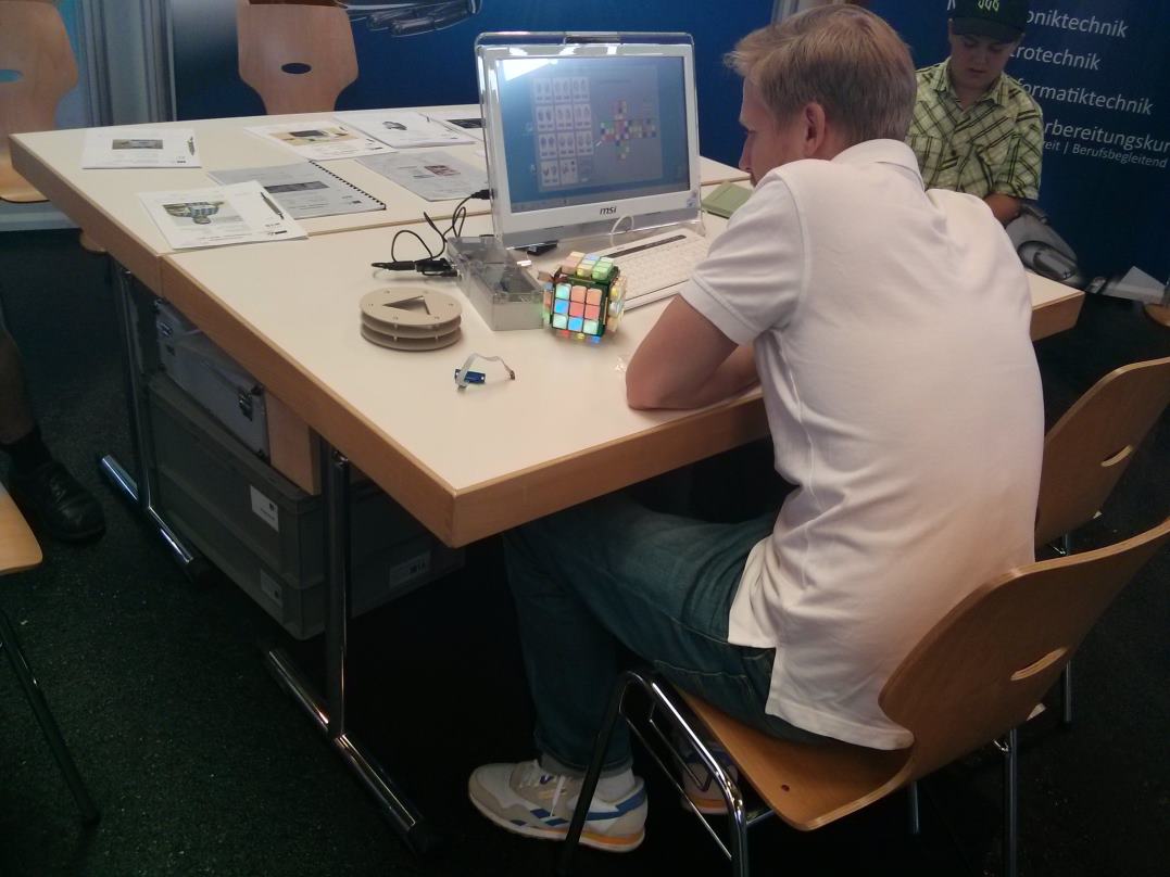
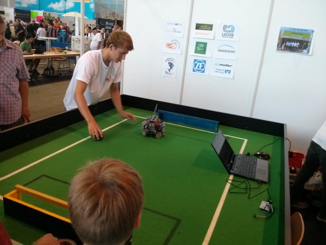
Various robots that could do things like following lines and playing football (quite badly ;)) and a computerised version of the Rubics Cube:

FR_Robot_LineFollow FR_Robot2 FR_RubicsCube FR_Robot_Football1

And then there was a whole stand where they  had “Pimp my Computer” type cases:

FR_PCCase1 FR_PCCase2FR_PCCase3

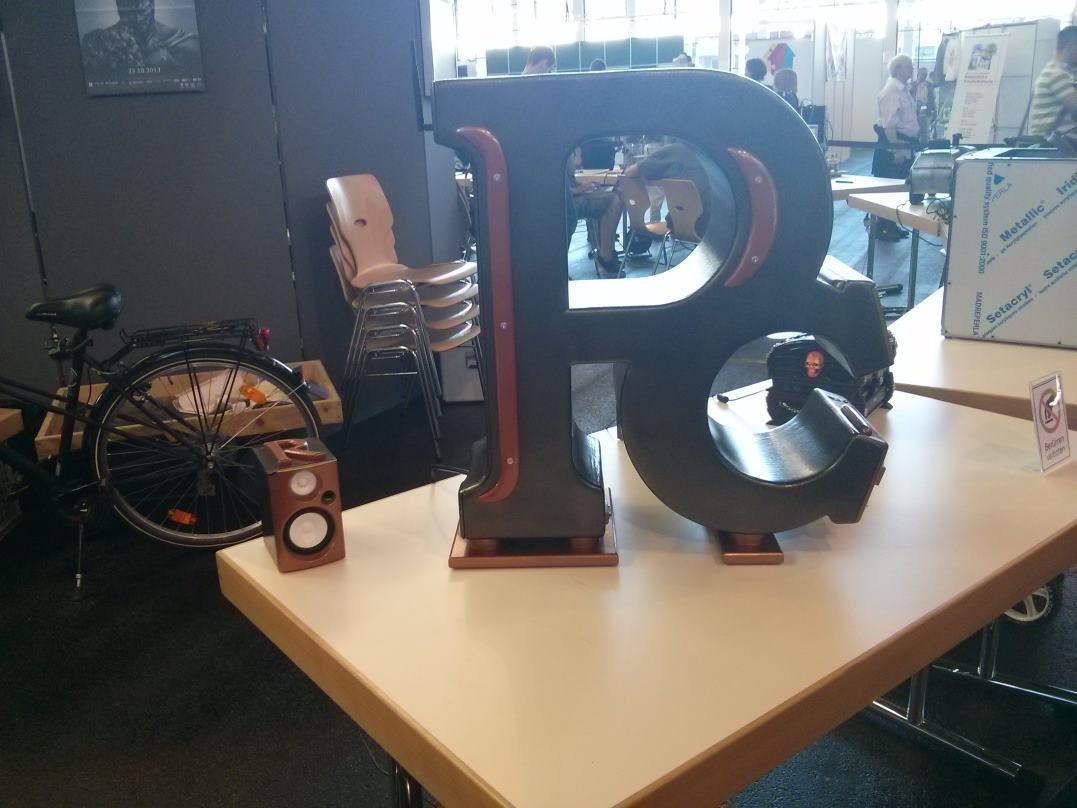
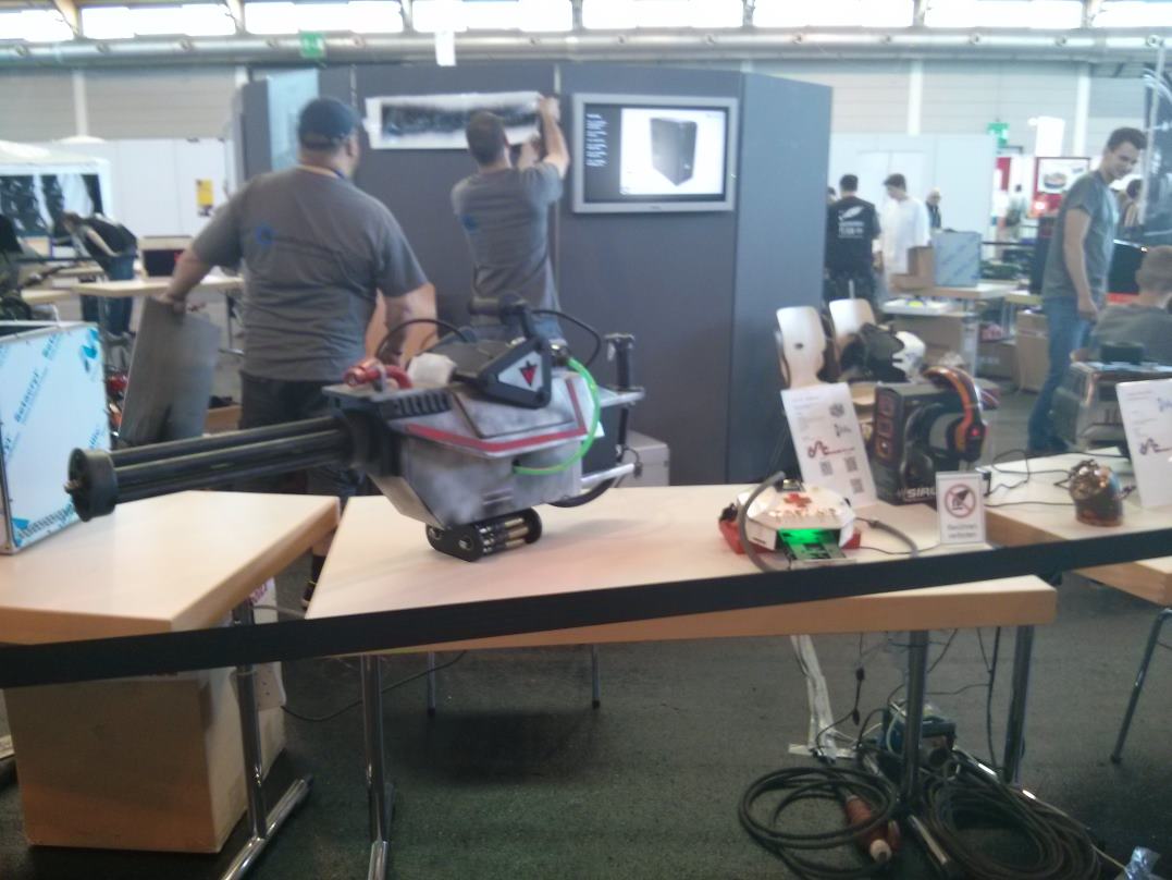
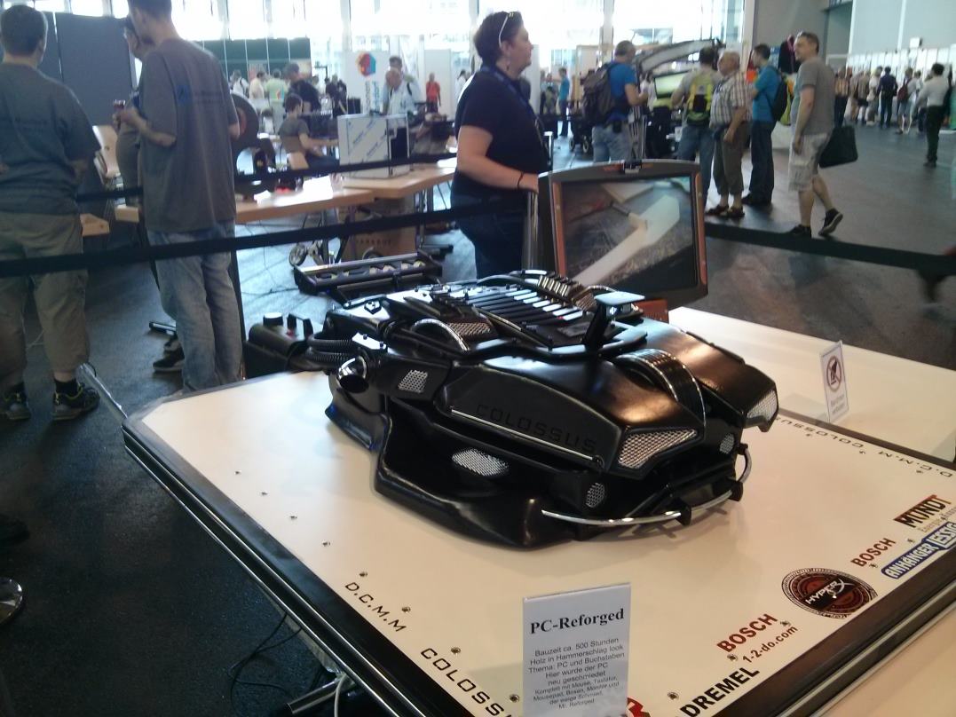
(None of these would fit on my desk – but maybe I’m missing the point!)

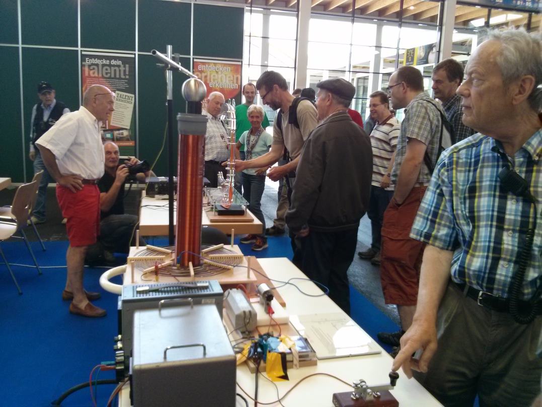
There was also some sort of musical instrument that you could wave your hand at to play each note. Unfortunately this was next to the Tesla coil, which kept setting it off!

FR_Music1 FR_Tesla1


Homebrew Data Interface

signalink

A while back, I borrowed a Tigertronics SignaLink to operate data modes. This worked really well, so I looked into buying one. They are quite expensive though… So I thought I’d build one.


To simplify things I decided to use my laptop’s internal soundcard. Data in and out seemed simple enough; I was going to use audio transformers to isolate the transceiver from the PC. I wanted the PTT line to be controlled by the right channel, because you can configure fldigi to put out the signal on the left channel and a constant tone on the right channel. That way I wouldn’t have to fiddle around with delays (that’s what the DLY control does on the SignaLink). My soundcard has a line in input (as opposed to a mic input) and the levels on line in / out are fairly consistent across soundcards, so I decided not to include level adjustments for TX and RX. I have included a trimmer on the output, but that is just set once and then left alone.

Something that made my PTT control more complicated was that unlike the SignaLink (which has a USB input), I did not have a source of power. Pulling PTT low (which is a digital input with a pullup) was going to prove challenging. So I designed something using a couple of MOSFETs that would be low power, and I could then essentially make it self powered. This was the circuit I came up with:

PSK Data Interface

You can see that the 47uF capacitor is charged by the PTT line via a diode. When an audio signal appears on the left channel the first MOSFET amplifies it to the point that it almost reaches the supply rails. The diode to the second MOSFET then presents the positive half of this to the second MOSFET, which switches on, pulling the PTT line low.  Because of the diode, the gate voltage stays high, and the MOSFET stays on. The only problem is that we now don’t have anything charging the capacitor up, so eventually this will drain below the point that it is able to turn the MOSFET on. Because we using large resistors on the first stage however, this will take several minutes, which is more than enough for our data transmission. When the audio tone is removed the leakage through the diode drains the gate voltage away and the MOSFET turns off (in practice this takes, at most, a few hundred milliseconds, but this means any audio tone will keep the second MOSFET turned on as long as the tone is present).

The final thing looked like this:

DataIF1

It’s not as good looking as a SignaLink, but I think it works just as well, and cost a lot less!

I am happy with this design, and it does work really well, but I would be interested to know if anyone can make something that uses even less power. [I did think about increasing the value of the resistors, but that isn’t really an option, because it then becomes very sensitive to noise]

I am using this for the PTT line on a transceiver, but I am sure this could be used for higher power switching. It would be interesting to see how much power (with a higher rated MOSFET) it could handle…

Yaesu FT-450 Master Controller

I quite like using data modes, and for this I use fldigi. I think one of the key things is to have a good setup, and so I have spent quite a lot of time creating macros, getting the CAT cable working, and building a homebrew data interface. For contests I use fldigi’s log, but for normal contacts I use DXKeeper. I found an application called fldigiDXLabsGateway.exe that will forward fldigi’s logged QSO to DXKeeper.

fldigiDXLabsGateway

One of the problems that I have had though was controlling the transceiver. I have tried using Commander (in the DXLab suite) and flrig but both seemed to cause fldigi to use the  PTT line via the CAT cable. The transceiver then didn’t want to get the audio via the data port. I did *sort of* get this working (you have to make sure the transceiver uses either USB DATA or LSB DATA mode), but it is unreliable at best, and fldigi and the rig control program seem to fight over the mode setting. If you want to try that though, click on the the link below:

Using Rig control program with fldigi

FT450MasterController Arch 2

In this configuration fldigi needs to control the rig using XML-RPC rather than Hamlib

The other problem is that fldigi doesn’t fill in the power field, so I had to manually update the record in DXKeeper. I try to use as little power as possible, so I am changing the RF power setting all the time. So, after trying various configurations, this was the one I settled with:

FT450MasterController using DXKeeper and gateway

In order to solve the problem of how to control the rig, I decided to go homebrew and create a transceiver controller. I looked at various architectures (and ran into various problems), but in the end I went for one that intercepted the messages going to the COM port. I did this by using a COM port loopback program called COM0COM.

COM0COM

COM0COM gives you pairs of COM ports (we only need one pair), and makes it appear as if the two COM ports are loopbacked to each other. This gives us lots of advantages over other ways of intercepting serial data – we don’t have to mess with drivers, and we don’t have to worry about serial ports disappearing when programs are closed (so we don’t have to worry too much about what order we run programs). I have tried COM0COM on Vista and Windows 7. On Vista you can use version 3.0 (after jumping through a few hoops), but Windows 7 needs a signed driver, so you have to use version 2.2 (and you still have to jump through a few hoops – mainly putting the OS into test mode, rebooting, installing, coming out of test mode and rebooting).

So the new architecture is:

FT450MasterController Arch 1

In order to put the power field in the log I intercept the TCP message sent by the fldigiDXLabGateway. Usually the gateway and DXKeeper both use port 52001, but I configured the gateway to use port 51001 so that I could intercept the message, add the power field, and then sent it to port 52001. The finished controller’s UI looked like this:

FT450MasterController1

Serial data from fldigi is intercepted by the master controller, and then forwarded to the radio. Same goes for data coming from the radio. The master controller also sends messages to the radio, so I created a queue. That way I can match replies up with requests, and ensure they go to the right place.

Now I’ve done this, I have a framework which I can use for any controls that I want. The only controls I have so far are RF power, AF gain, and controlling what the CS/Voice button does  -in this case play a pre-recorded voice message (SSB / phone) or output a 10W carrier (for tuning / swr display).