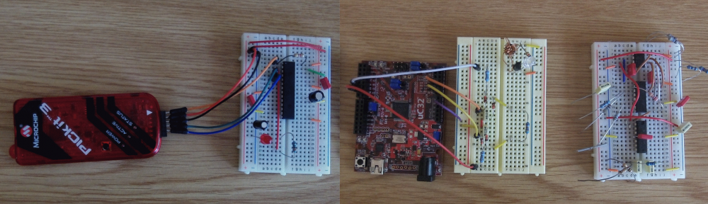
The aim of this post is to describe how to put a PIC32 chip on a breadboard (I’m using a PIC32MX250F128B), connect up the PICkit3 between the board and the PC, and then debug a really simple program (that just flashes an LED).
The IDE we’ll be using is MPLABX with the XC32 compiler. You need to make sure these are installed first, if you haven’t done so already. To get these visit:
http://www.microchip.com/pagehandler/en-us/family/mplabx/#downloads
Install MPLABX first, and then install XC32.
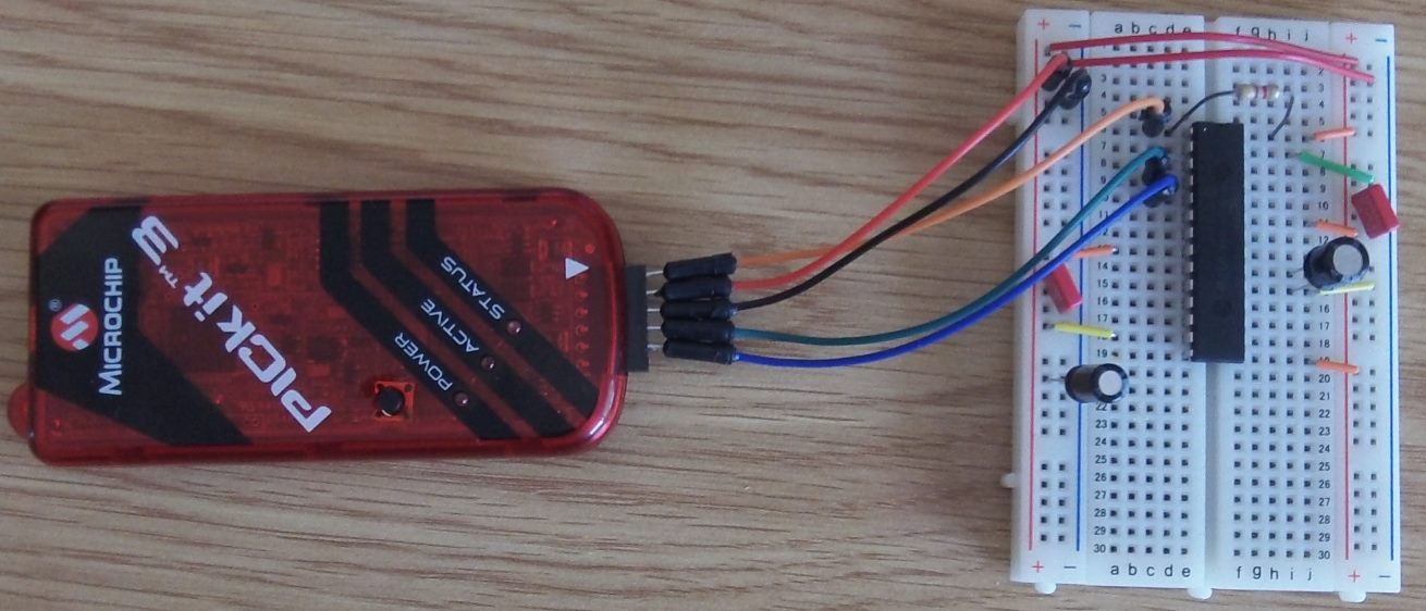
This is the setup for the breadboard connected to the PICkit3:
The schematic for this is:
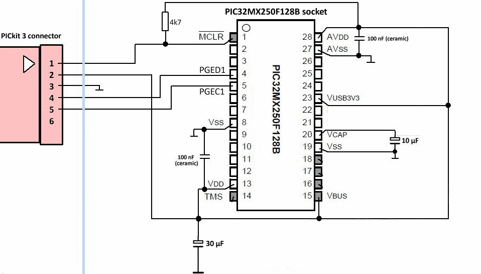
[I got this from https://sites.google.com/site/pcusbprojects/5-custom-projects/r-pickit-3-header-for-pic32mx250f128b-programming. I have removed the voltage regulator because I will be powering the chip from the PICkit3]
You then connect this up to the PC with a USB cable, and start the MPLABX IDE.
To create our simple project, select New Project from the file menu. Select Microchip Embedded, Standalone Project from the categories / projects windows. Press Next.
Select the device, in my case 32 bit MCUS / PIC32MX250F128B. Press Next.
Select PICkit3 as the tool. Press Next.
Select XC32 as the compiler. Press Next.
Choose a name for the project. I chose Blink1 Press Finish.
In the Projects window, right click on Source Files. and select New, C New Main File… and enter the name “main” (instead of newmain). Press Finish.
Before we run this on the real device, we need to make sure that the chip will be powered from the PICkit3. To do this you need to select Project Properties (Blink1) from the file menu. In the left hand window (Categories) you need to select PICkit3. On the right you will then see a dropdown labelled Option Categories. From this select Power. In the options below you will now see Power target circuit from PICkit3. Check the checkbox. Leave the voltage level as 3.25. Press OK.
We need to build the project, program the device, and then start the debugger. The easiest way to do this is select Debug Project (Blink1) from the Debug menu. MPLABX will then build, program and run our code. You may get the following warning:
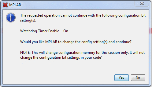
…just press Yes.
If everything is working ok there will be a set of windows at the bottom labelled “Blink1 (Build, Load, …)”, “Debugger Console” and “PICkit3”. In the PICkit3 window the last few lines should read:
Programming…
Programming/Verify complete
Running
Not very exciting after all that work! And no evidence that it really is working. Lets add a breakpoint.
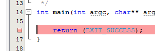
Open main.c in the source files folder by double clicking it. Click on the grey sidebar where it says 16. That will set a breakpoint at the line which will look like:
You should notice that the PICkit3 window has a red line of text that says:
The PICkit 3 does not support the ability to set breakpoints while the devices is running. The breakpoint will be applied prior to the next time you run the device.
This is important. It means that you can only set breakpoints:
- Before you’ve started the debugger, or
- When you have stopped at an existing breakpoint.
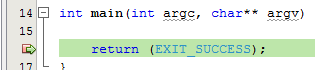
If you click on Debug Project (Blink1) again then the program should restart and (eventually) the breakpoint will be hit. That looks like:
Still not very exciting. But at least we can see that something is happening. It’s probably worth having a quick look at what you do when you are stopped at a breakpoint. On the Window menu there is a Debugging option. From here we can see variables and the disassembly for instance. We can also see the contents of memory and registers on the PIC Memory Views menu item… but detailed explanations would take far too long to go through now. I’ll do that in a later post.
Anyway, that’s enough for now. Next time we’ll modify the circuit to add an LED, and make it blink – after all that is the name of the project!