PIC12F1840: Blink using timer0 and interrupts

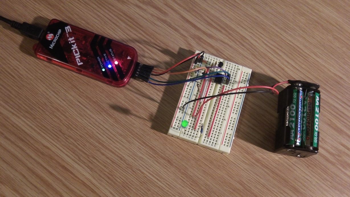
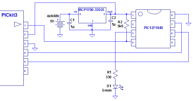
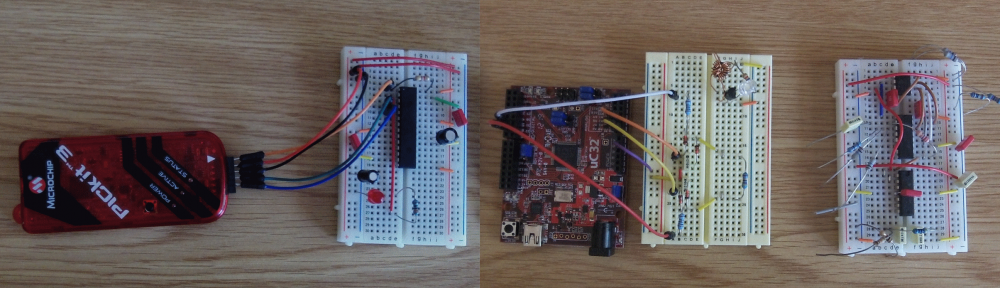
A much better way to blink the LED is to use a timer, and rely on the timer generating an interrupt on the timer expiry. This is more accurate, and also doesn’t hog the CPU. Using the same setup as before (using the PIC12F1840), we change the code as follows:

#include <xc.h>
#include <stdio.h>
#include <stdlib.h>

// CONFIG1
#pragma config FOSC = INTOSC // Oscillator Selection (INTOSC oscillator: I/O function on CLKIN pin)
#pragma config WDTE = OFF // Watchdog Timer Enable (WDT disabled)
#pragma config PWRTE = OFF // Power-up Timer Enable (PWRT disabled)
#pragma config MCLRE = ON // MCLR Pin Function Select (MCLR/VPP pin function is MCLR)
#pragma config CP = OFF // Flash Program Memory Code Protection (Program memory code protection is disabled)
#pragma config CPD = OFF // Data Memory Code Protection (Data memory code protection is disabled)
#pragma config BOREN = ON // Brown-out Reset Enable (Brown-out Reset enabled)
#pragma config CLKOUTEN = OFF // Clock Out Enable (CLKOUT function is disabled. I/O or oscillator function on the CLKOUT pin)
#pragma config IESO = ON // Internal/External Switchover (Internal/External Switchover mode is enabled)
#pragma config FCMEN = ON // Fail-Safe Clock Monitor Enable (Fail-Safe Clock Monitor is enabled)

// CONFIG2
#pragma config WRT = OFF // Flash Memory Self-Write Protection (Write protection off)
#pragma config PLLEN = ON // PLL Enable (4x PLL enabled)
#pragma config STVREN = ON // Stack Overflow/Underflow Reset Enable (Stack Overflow or Underflow will cause a Reset)
#pragma config BORV = LO // Brown-out Reset Voltage Selection (Brown-out Reset Voltage (Vbor), low trip point selected.)
#pragma config LVP = OFF // Low-Voltage Programming Enable (Low-voltage programming enabled)

int counter = 0;

int main(int argc, char** argv)
{
  TRISA = 0xEF; // Set RA4 pin as output

  OPTION_REG = 0xC7; //Set prescaler to 256
  TMR0 = 0xFF; //Timer0 module register
  TMR0IE = 1;
  ei(); //Enable all configured interrupts

  while (1); //Loop forever

  return (EXIT_SUCCESS);
}

void interrupt Timer0_ISR(void)
{
  counter++;
  RA4 = counter & 1;  //Toggle the LED
  TMR0IF = 0;         //Clear the timer interrupt flag
}

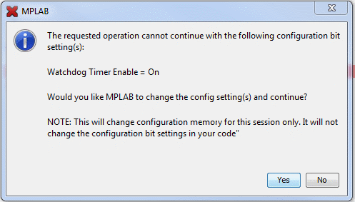
Notice that we have also included a configuration section. Apart from anything else, this will get rid of the annoying messages about the low power programming and watchdog (the watchdog is a very useful feature, but that will have to wait for another day). There is an easy way to generate the configuration, which is to select Configuration Bits from the Window /  PIC Memory Views menu item. From there you can change the options and the press the Generate Source Code to Output button.

Using the PIC12F1840

The PIC32 chip worked well, but this time I’m going to use a much cheaper (and smaller) device. The PIC12F1840 comes in an 8 pin DIP package. I’m going to do the same code – flash an LED – the principle is same as for the PIC32 chip, so we’ll use a similar circuit to program it:

102_0104

This time though, we’re going to use an external supply rather than powering it from the PICkit3. Hence the battery pack. That’s 4 Ni-Mh cells, and produces just over 5V. We could power the PIC directly, but the batteries could theoretically provide over 5.5V when fully charged, so I’m going to use voltage regulator to bring the voltage down to 3.3V. Here is the schematic:

PIC12F1840Pgm

After I built this, I measured the input voltage:

Blink2_Vin

and output voltage:

Blink2_Vout

The regulator is supposed to output 3.3V, so that’s spot on.

We’re going to need a different compiler, so I have downloaded and installed the XC8 compiler.The program is essentially the same as Blink1 for the PIC32 chip, but is coded slightly differently:

int main(int argc, char** argv)
{
  TRISA = 0xEF; // Set RA4 pin as output

  // Loop to flash an LED on RA4 (pin 3)
  while(1)
  {
    RA4 = 1; // Set RA4 high
    // Insert some delay
    int i = 10000;
    while(i--);

    RA4 = 0; // Set RA4 low
    // Insert some delay
    i = 10000;
    while(i--);
  }

  return (EXIT_SUCCESS);
}

We need to add the following include statement at the top of the file:

#include <xc.h>

This will choose the correct include file (in this case pic12f1840.h).

You’ll notice that the delay loop (which I’m still not proud of) has less iterations than the PIC32 chip. This chip is considerably slower! By default the device is running at 500KHz. We can increase this to 32MHz, but the power consumption will be much higher.

One advantage of powering the device externally is that we can disconnect the programmer and the code will still run. In order to do this we need to select Run Project (Blink2) from the run menu. The code, which is stored flash memory even when the power is off, will then happily just start running as soon as the battery is connected.

With the PIC running just off the battery, I thought I’d check the current consumption. The current fluctuates between 0.16mA and 3.34mA depending on whether the LED is off or on. Given that the voltage drop across  the LED should be about 1.8V, 3mA is what I would expect to be going through the LED. As you can see though, it doesn’t draw much current when it is running. With proper use of sleep modes it is possible to get this device to use much less current when operating.

Setting up the PICkit3 with MPLABX (Part 2)

Last time we saw how to set up the PICkit3 with MPLABX and get a very simple program running. The program didn’t actually do anything though! So this time we are going to add an LED to the breadboard and make the LED blink on and off.

The first thing we need to do is add an LED to the board:

102_0096

The LED is connected via a 330 ohm resistor from pin 2 (RA0) to GND.

We then need to modify our code. We are going to modify main function in main.c as follows:

int main(int argc, char** argv)
{
    TRISA = 0xFFFE; // Set RA0 pin as output

    // Loop to flash an LED on RA0 (pin 2)
    while(1)
    {
        PORTASET = 1;          // Set RA0 high
        // Insert some delay
        int i = 100000;
        while(i--);

        PORTACLR = 0;          // Set RA0 low
        // Insert some delay
        i = 100000;
        while(i--);
    }

    return (EXIT_SUCCESS);
}

For this to work you need to add the following include at the top of the file:

#include <p32xxxx.h>

Now when we run the project from the Run menu, the LED should blink on and off.

Note:

The delay loop is bad code. I’m not proud of that, and I wouldn’t suggest using it in your projects! I’ll show you how to do it properly in a future post.

Setting up the PICkit3 with MPLABX (Part 1)

The aim of this post is to describe how to put a PIC32 chip on a breadboard (I’m using a PIC32MX250F128B), connect up the PICkit3 between the board and the PC, and then debug a really simple program (that just flashes an LED).

The IDE we’ll be using is MPLABX with the XC32 compiler. You need to make sure these are installed first, if you haven’t done so already. To get these visit:

http://www.microchip.com/pagehandler/en-us/family/mplabx/#downloads

Install MPLABX first, and then install XC32.

This is the setup for the breadboard connected to the PICkit3:

PICkit3AndBoard

The schematic for this is:

ProgramCircuit

[I got this from https://sites.google.com/site/pcusbprojects/5-custom-projects/r-pickit-3-header-for-pic32mx250f128b-programming. I have removed the voltage regulator because I will be powering the chip from the PICkit3]

You then connect this up to the PC with a USB cable, and start the MPLABX IDE.

To create our simple project, select New Project from the file menu. Select Microchip Embedded, Standalone Project from the categories / projects windows. Press Next.

Select the device, in my case 32 bit MCUS / PIC32MX250F128B. Press Next.

Select PICkit3 as the tool. Press Next.

Select XC32 as the compiler. Press Next.

Choose a name for the project. I chose Blink1 Press Finish.

In the Projects window, right click on Source Files. and select NewC New Main File… and enter the name “main” (instead of newmain). Press Finish.

Before we run this on the real device, we need to make sure that the chip will be powered from the PICkit3. To do this you need to select Project Properties (Blink1) from the file menu. In the left hand window (Categories) you need to select PICkit3. On the right you will then see a dropdown labelled Option Categories. From this select Power. In the options below you will now see Power target circuit from PICkit3. Check the checkbox. Leave the voltage level as 3.25. Press OK.

We need to build the project, program the device, and then start the debugger. The easiest way to do this is select Debug Project (Blink1) from the Debug menu. MPLABX will then build, program and run our code. You may get the following warning:

WatchdogWarning

…just press Yes.

If everything is working ok there will be a set of windows at the bottom labelled “Blink1 (Build, Load, …)”, “Debugger Console” and “PICkit3”. In the PICkit3 window the last few lines should read:

Programming…
Programming/Verify complete

Running

Not very exciting after all that work! And no evidence that it really is working. Lets add a breakpoint.

Open main.c in the source files folder by double clicking it. Click on the grey sidebar where it says 16. That will set a breakpoint at the line which will look like:

Breakpoint

You should notice that the PICkit3 window has a red line of text that says:

The PICkit 3 does not support the ability to set breakpoints while the devices is running. The breakpoint will be applied prior to the next time you run the device.

This is important. It means that you can only set breakpoints:

  • Before you’ve started the debugger, or
  • When you have stopped at an existing breakpoint.

If you click on Debug Project (Blink1) again then the program should restart and (eventually) the breakpoint will be hit. That looks like:

HitBreakpoint

Still not very exciting. But at least we can see that something is happening. It’s probably worth having a quick look at what you do when you are stopped at a breakpoint. On the Window menu there is a Debugging option. From here we can see variables and the disassembly for instance. We can also see the contents of memory and registers on the PIC Memory Views menu item… but detailed explanations would take far too long to go through now. I’ll do that in a later post.

Anyway, that’s enough for now. Next time we’ll modify the circuit to add an LED, and make it blink – after all that is the name of the project!