The PIC32 chip worked well, but this time I’m going to use a much cheaper (and smaller) device. The PIC12F1840 comes in an 8 pin DIP package. I’m going to do the same code – flash an LED – the principle is same as for the PIC32 chip, so we’ll use a similar circuit to program it:
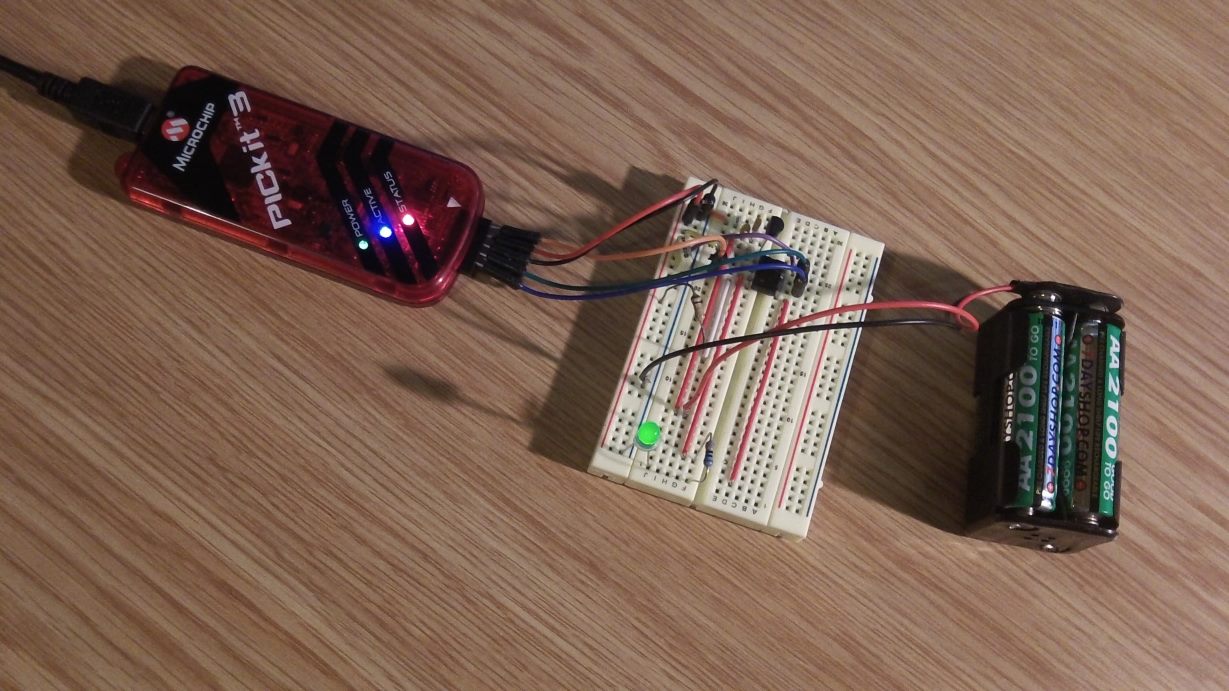
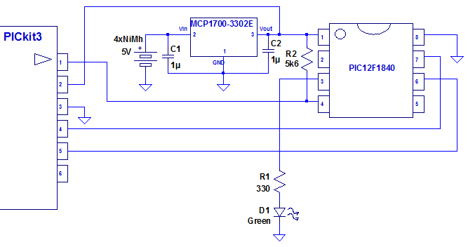
This time though, we’re going to use an external supply rather than powering it from the PICkit3. Hence the battery pack. That’s 4 Ni-Mh cells, and produces just over 5V. We could power the PIC directly, but the batteries could theoretically provide over 5.5V when fully charged, so I’m going to use voltage regulator to bring the voltage down to 3.3V. Here is the schematic:
After I built this, I measured the input voltage:

and output voltage:

The regulator is supposed to output 3.3V, so that’s spot on.
We’re going to need a different compiler, so I have downloaded and installed the XC8 compiler.The program is essentially the same as Blink1 for the PIC32 chip, but is coded slightly differently:
int main(int argc, char** argv)
{
  TRISA = 0xEF; // Set RA4 pin as output

  // Loop to flash an LED on RA4 (pin 3)
  while(1)
  {
    RA4 = 1; // Set RA4 high
    // Insert some delay
    int i = 10000;
    while(i--);

    RA4 = 0; // Set RA4 low
    // Insert some delay
    i = 10000;
    while(i--);
  }

  return (EXIT_SUCCESS);
}
We need to add the following include statement at the top of the file:
#include <xc.h>
This will choose the correct include file (in this case pic12f1840.h).
You’ll notice that the delay loop (which I’m still not proud of) has less iterations than the PIC32 chip. This chip is considerably slower! By default the device is running at 500KHz. We can increase this to 32MHz, but the power consumption will be much higher.
One advantage of powering the device externally is that we can disconnect the programmer and the code will still run. In order to do this we need to select Run Project (Blink2) from the run menu. The code, which is stored flash memory even when the power is off, will then happily just start running as soon as the battery is connected.
With the PIC running just off the battery, I thought I’d check the current consumption. The current fluctuates between 0.16mA and 3.34mA depending on whether the LED is off or on. Given that the voltage drop across the LED should be about 1.8V, 3mA is what I would expect to be going through the LED. As you can see though, it doesn’t draw much current when it is running. With proper use of sleep modes it is possible to get this device to use much less current when operating.