No hack these days would be complete without the inclusion of a mint tin (although usually as a case); so we are going to build a capacitor with two tins, and compare it’s measured value against it’s calculated value.
Any two flat bits of metal would do, but I had two of these tins to hand, so that’s what I used.
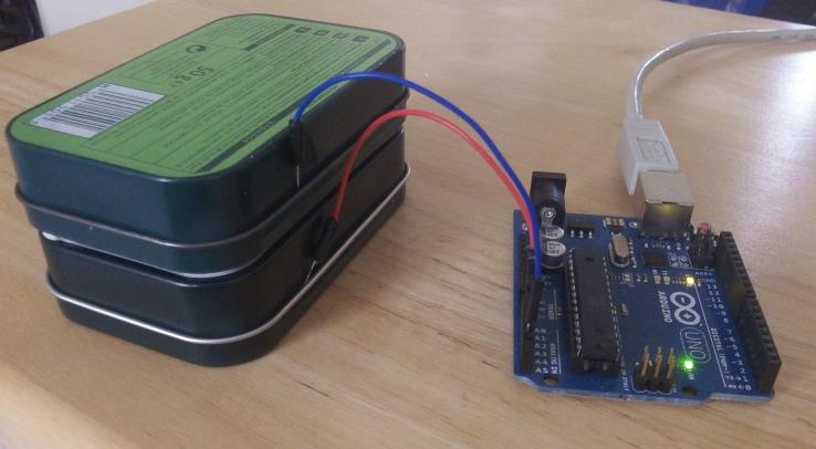
The two “plates” of the capacitor need to be spaced apart – I chose 3mm – which I did with four small blobs of blu tack in each corner and then squashed it down until I had a fairly even 3mm spacing. I then jammed the wires into the edge of the tin, making sure they made a reasonable contact, and plugged the other ends into the Arduino. On the serial monitor I got the following reading:
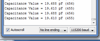
About 19.6pF. Next, to calculate what it should be. The formula for a capacitor is:

Our tin is about 58mm x 93mm, which gives us an area of 0.005394 m2. The distance is 0.003 m. ε0 is about 8.854×10⁻¹². If we put this into the formula above, this gives us a capacitance of about 15.9pF.
Taking into account stray capacitance and inaccuracies in our measurements, this is close enough to the 19.6pF that we measured.
I reduced the air gap to about 1mm and the measured value went up to about 45pF – which again is what we would expect.
If you put different materials between the plates the capacitance will be higher – paper for instance has a relative permittivity of 3.85 (see wikipedia).
How about two currency coins (biggest in size) with a very thin wax layer in between? Or wet paper in between. Make sure though, to use only distilled water for wetting paper, otherwise it will be a very ‘leaky’ capacitor. 😛
Hi! In your picture for this experiment, I don’t see the C1 (30pF), I just see the CT, is that by design? I’m assuming if you don’t have C1 in your design, the measurement will not be accurate as the CT will always charge up to digital HIGH. Pls let me know what am I missing.
I’m relying on the stray capacitance of the Arduino / board, which is about 30pF. In the code it is defined as IN_STRAY_CAP_TO_GND. In the main article I suggest calibrating this as otherwise the measurement won’t be very accurate – on my board this turned out to be 24.48pF.
Thanks! I’m getting strange results lately with a similar experiment as yours. I’m trying to measure a capacitance of a liquid and even with liquid at rest, the value read by Arduino fluctuates a lot, I even tried changing sampling time (500ms to 16sec), and even read the value at different times (1000ms to 4000ms) before writing digital high. The capacitance when I measure through my capacitance meter it is in the range of 50-90pF so I was expecting it to charge/discharge very quickly. Any ideas/thoughts to troubleshoot/debug is appreciated. I tried with a couple of Arduino boards but the resulting pattern didn’t change.
Thanks!
@Raj: reading single samples at larger time intervals will not help to reduce the noise. But it can be removed by taking many samples, sum them up and divide by the number of samples taken. This removes the noise and provides a stable value.