Capacitance Meter Temperature Sensitivity

One of the comments was from Jim, who was interested in the temperature sensitivity of the capacatiance meter. So I’ve tested it. I took some measurements of a selection of capacitors. I then put the Arduino board in the fridge at 4C for an hour, and repeated the test. I tried to do this as quickly as possible, so the board didn’t warm up too much. The results were as follows:

Continue reading

Capacitance Meter Mk II

I was blown away with the interest in the Capacitance Meter for the Arduino Uno, and that encouraged me to think about how I could improve it.

CapMeterMkII

Scott made a comment on the Hackaday post, and suggested using the internal pullup resistor to cover higher capacitances. I had initially ruled that out because it wouldn’t work for low value capacitors (less than about 1nF). But thinking about it again, I realized that this method could be used to extend the range up to uF values. By combining this with the method in the Mk I Capacitance meter, I could make a capacitance meter that could measure from 1pF to over 1000uF – with no external components!

Actually getting this to work proved slightly more complicated than I first thought. The basic idea was going to be:

  1. Test the capacitor using the stray capacitance method. If the capacitor is less than 1nF then we are done.
  2. Otherwise, we start charging the capacitor using the internal pullup.
  3. After a certain amount of time (maybe the RC time constant), the capacitor will have reached a certain voltage.
  4. Using the charge time and voltage (or more specifically  the ratio of the capacitor voltage to the charging voltage) we can work out the capacitance.

The time to charge larger capacitors would be in the order of milliseconds. This would be quite easy to measure with a reasonable degree of accuracy. But the RC time constant of a 1nF capacitor with a 30k pullup is about 30us. Which is more difficult to measure accurately. I thought about using interrupts, and using a hand-crafted ADC conversion method (analogRead takes about 100us – and you can do the conversion much faster than this), but I didn’t want the code to get too complicated, and I wanted to stick to the standard Arduino routines. So I came up the the following code:

View Code

const int OUT_PIN = A2;
const int IN_PIN = A0;

//Capacitance between IN_PIN and Ground
//Stray capacitance value will vary from board to board.
//Calibrate this value using known capacitor.
const float IN_STRAY_CAP_TO_GND = 24.48;
const float IN_CAP_TO_GND  = IN_STRAY_CAP_TO_GND;
//Pullup resistance will vary depending on board.
//Calibrate this with known capacitor.
const float R_PULLUP = 34.8;  //in k ohms
const int MAX_ADC_VALUE = 1023;

void setup()
{
  pinMode(OUT_PIN, OUTPUT);
  //digitalWrite(OUT_PIN, LOW);  //This is the default state for outputs
  pinMode(IN_PIN, OUTPUT);
  //digitalWrite(IN_PIN, LOW);

  Serial.begin(115200);
}

void loop()
{
    //Capacitor under test between OUT_PIN and IN_PIN
    //Rising high edge on OUT_PIN
    pinMode(IN_PIN, INPUT);
    digitalWrite(OUT_PIN, HIGH);
    int val = analogRead(IN_PIN);
    digitalWrite(OUT_PIN, LOW);

    if (val < 1000)
    {
      //Low value capacitor
      //Clear everything for next measurement
      pinMode(IN_PIN, OUTPUT);

      //Calculate and print result

      float capacitance = (float)val * IN_CAP_TO_GND / (float)(MAX_ADC_VALUE - val);

      Serial.print(F("Capacitance Value = "));
      Serial.print(capacitance, 3);
      Serial.print(F(" pF ("));
      Serial.print(val);
      Serial.println(F(") "));
    }
    else
    {
      //Big capacitor - so use RC charging method

      //discharge the capacitor (from low capacitance test)
      pinMode(IN_PIN, OUTPUT);
      delay(1);

      //Start charging the capacitor with the internal pullup
      pinMode(OUT_PIN, INPUT_PULLUP);
      unsigned long u1 = micros();
      unsigned long t;
      int digVal;

      //Charge to a fairly arbitrary level mid way between 0 and 5V
      //Best not to use analogRead() here because it's not really quick enough
      do
      {
        digVal = digitalRead(OUT_PIN);
        unsigned long u2 = micros();
        t = u2 > u1 ? u2 - u1 : u1 - u2;
      } while ((digVal < 1) && (t < 400000L));

      pinMode(OUT_PIN, INPUT);  //Stop charging
      //Now we can read the level the capacitor has charged up to
      val = analogRead(OUT_PIN);

      //Discharge capacitor for next measurement
      digitalWrite(IN_PIN, HIGH);
      int dischargeTime = (int)(t / 1000L) * 5;
      delay(dischargeTime);    //discharge slowly to start with
      pinMode(OUT_PIN, OUTPUT);  //discharge remainder quickly
      digitalWrite(OUT_PIN, LOW);
      digitalWrite(IN_PIN, LOW);

      //Calculate and print result
      float capacitance = -(float)t / R_PULLUP
                              / log(1.0 - (float)val / (float)MAX_ADC_VALUE);

      Serial.print(F("Capacitance Value = "));
      if (capacitance > 1000.0)
      {
        Serial.print(capacitance / 1000.0, 2);
        Serial.print(F(" uF"));
      }
      else
      {
        Serial.print(capacitance, 2);
        Serial.print(F(" nF"));
      }

      Serial.print(F(" ("));
      Serial.print(digVal == 1 ? F("Normal") : F("HighVal"));
      Serial.print(F(", t= "));
      Serial.print(t);
      Serial.print(F(" us, ADC= "));
      Serial.print(val);
      Serial.println(F(")"));
    }
    while (millis() % 1000 != 0)
      ;    
}

I’ll try to explain why I coded it this way… I tried using analogRead() to determine when the capacitor had charged up to a certain value. This could work, but analogRead() is very slow so I decided to use the input as a digital input to start with. When the input gets to about 2.5V the input will change from 0 to 1 and we stop charging the capacitor. At this point we really can’t be sure what the the voltage is across the capacitor, so we use analogRead to get an accurate value. We have taken timestamps at the start and end of the charging process, so now we have everything we need to determine the capacitance. The maths behind this is as follows:

RC_Charging1

For the circuit above, the formulas that we need are:

RCFormula1

Initially I assumed that the pullup resistor had a value of 30k. This won’t be correct and should be calibrated using a capacitor of a known value. Something around about 100nF – 1uF should give a good measurement (don’t use an electrolytic – these tend to have very poor tolerance, typically -20%, +80%!). By putting these numbers into the last formula, we can determine the actual pullup resistance.

I used a 1uF capacitor and got the following result:

Capacitance Value = 1.00 uF (Normal, t= 24704 us, ADC= 520)

[Note that at this point the measured capacitance probably won’t be 1.00uF]

Putting these numbers (C = 1e-6F, t = 0.024704s, Vc=520, Vin=1023) into the last formula gives us the result: R = 34.80 kΩ (34800Ω). For C we should use the expected value (1.00uF) rather than the measured value which, as previously stated, is likely to be different until we have done the calibration.

I then tested this with various capacitors.

dec9caps

These were my results:

Results

Capacitor Reading
5pF +-.5pF 5.404 pF (185)
101J 102.000 pF (825)
471K 457.117 pF (971)
102K 0.95 nF (Normal, t= 32 us, ADC= 636)
222K 2.07 nF (Normal, t= 64 us, ADC= 602)
103K 10.50 nF (Normal, t= 272 us, ADC= 537)
104K 112.39 nF (Normal, t= 2800 us, ADC= 523)
105K 986.04 nF (Normal, t= 24428 us, ADC= 521)
106K (tant.) 11.75 uF (Normal, t= 291124 us, ADC= 521)
4.7u (elec.) 5.02 uF (Normal, t= 124108 us, ADC= 520)
10u (elec.) 12.12 uF (Normal, t= 299352 us, ADC= 520)
220u (elec.) 224.77 uF (HighVal, t= 400004 us, ADC= 51)
1000u (elec.) 1170.11 uF (HighVal, t= 400000 us, ADC= 10)

When testing electrolytics make sure that you connect the +ve end to A2 and the negative end to A0.

I’m not sure how accurate this is, but I will look into this (and try to improve it if necessary) when I get a chance.

Note:
I've turned this into a library for the Arduino - so that's the easiest way to measure capacitance.
Search for "capacitor" in the Arduino IDE library manager (Tools menu, Manage Libraries...).

Capacitance measurement with the Arduino Uno

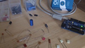
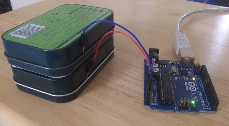
You can buy meters, like this one for instance:

Peak_LCR40

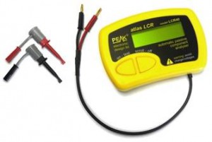
that measure capacitance, but where’s the fun in that?!

If you’ve got an Arduino, why not build one instead?

Note:
I've turned this into a library for the Arduino - so that's the easiest way to measure capacitance.
Search for "capacitor" in the Arduino IDE library manager (Tools menu, Manage Libraries...).

Update: Thank you for all the interest in this article! I have managed to increase the range, so it can measure capacitances of less than 1pF to over 1000uF , still with no external components! I’ve called this the Capacitance Meter Mk II.

There are lots of examples of how to do this on the internet, but I’m going to suggest an incredibly simple way to it. Let’s start with the theory.

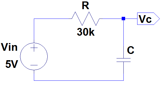
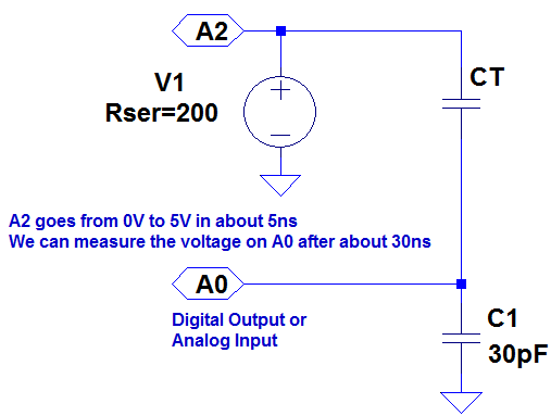
Consider the following circuit:

SimpleCapacitanceTester

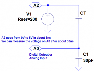
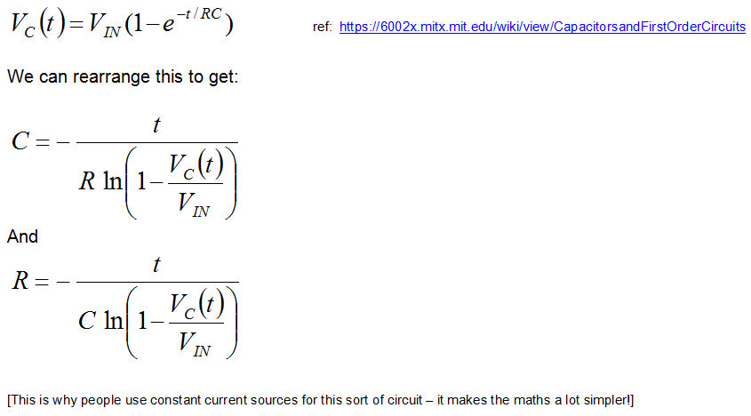
CT is the capacitor under test. We start with both capacitors discharged and A2 at 0 volts. When we raise A2 to 5 volts a current will flow through both capacitors. The voltage on A0 will settle to within 1% of it’s final value within 30ns. The value that A0 will settle to is proportional to the ratio of CT divided by the total capacitance, C1 + CT. The formulas that we are going to need are:

CapTestFormulas3

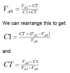
We will use the ADC to measure VA0. VA2 is actually 5 volts,  so VA0 will vary from 0 to 5 volts, but we can use the ADC value instead, to make the calculations easier. Obviously we should then use the maximum ADC value (1023) for VA2. The ADC readings we can expect will range from about 33 for CT = 1pF to about 993 for CT = 1nF (1000pF).

So now we are ready to build the circuit and write the code. Right? Well, not quite. In the circuit above we have specified C1 as 30pF. But the Arduino will have some stray capacitance on the board and in the micro-controller. About 30pF of stray capacitance. We’re going to use this to make our circuit simpler – we are going to remove C1. But we need to work out how much stray capacitance there is, so we can plug it into the formulas above. But first, we’ll build the circuit and write the code.

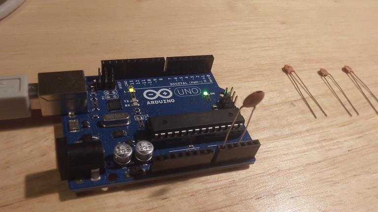
The circuit is surprisingly easy. In fact there isn’t a circuit now. We’re going to use the Arduino as follows:

CapTestBoard1

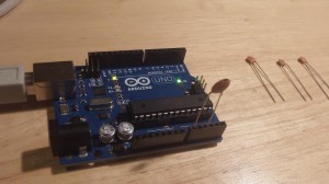
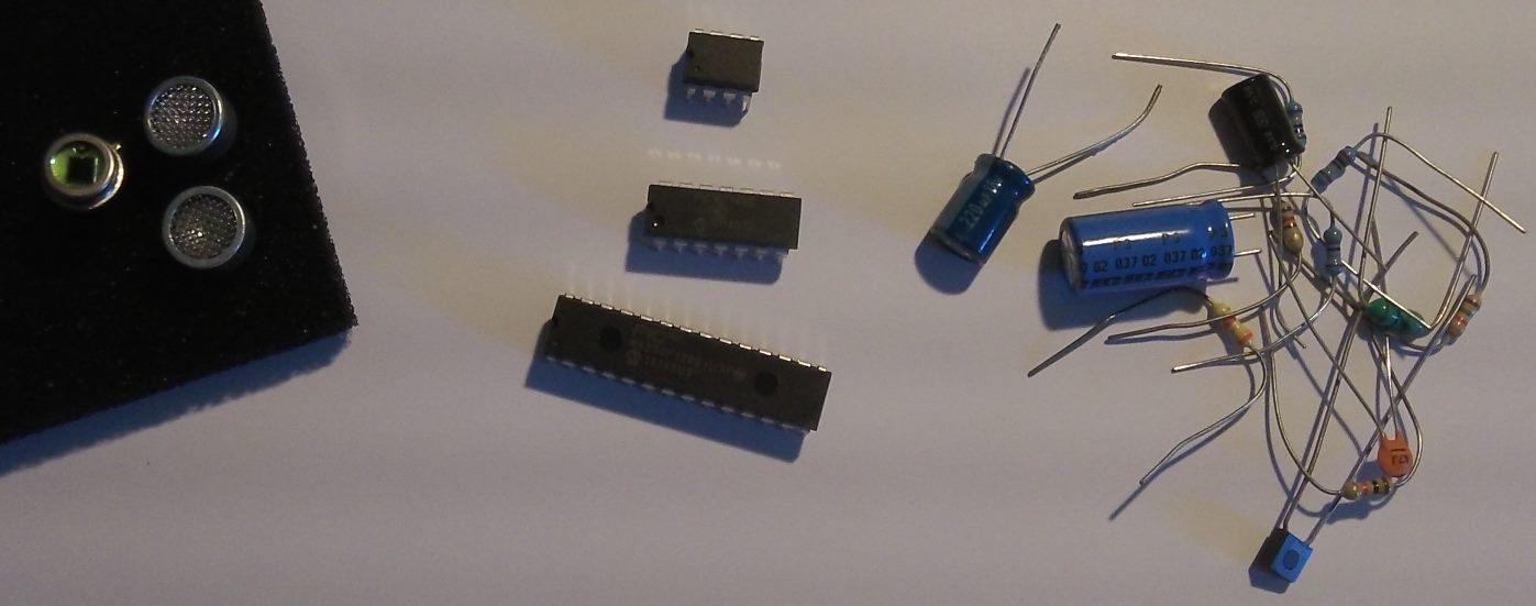
The capacitor is the capacitor under test between A0 and A2. The capacitors on the right are the capacitors that I am going to test a bit later on.

The code looks like this:

const int OUT_PIN = A2;
const int IN_PIN = A0;

//Capacitance between IN_PIN and Ground
//Stray capacitance is always present. Extra capacitance can be added to
//allow higher capacitance to be measured.
const float IN_STRAY_CAP_TO_GND = 24.48; //initially this was 30.00
const float IN_EXTRA_CAP_TO_GND = 0.0;
const float IN_CAP_TO_GND  = IN_STRAY_CAP_TO_GND + IN_EXTRA_CAP_TO_GND;
const int MAX_ADC_VALUE = 1023;

void setup()
{
  pinMode(OUT_PIN, OUTPUT);
  //digitalWrite(OUT_PIN, LOW);  //This is the default state for outputs
  pinMode(IN_PIN, OUTPUT);
  //digitalWrite(IN_PIN, LOW);

  Serial.begin(115200);
}

void loop()
{
  //Capacitor under test between OUT_PIN and IN_PIN
  //Rising high edge on OUT_PIN
  pinMode(IN_PIN, INPUT);
  digitalWrite(OUT_PIN, HIGH);
  int val = analogRead(IN_PIN);

  //Clear everything for next measurement
  digitalWrite(OUT_PIN, LOW);
  pinMode(IN_PIN, OUTPUT);

  //Calculate and print result

  float capacitance = (float)val * IN_CAP_TO_GND / (float)(MAX_ADC_VALUE - val);

  Serial.print(F("Capacitance Value = "));
  Serial.print(capacitance, 3);
  Serial.print(F(" pF ("));
  Serial.print(val);
  Serial.println(F(") "));

  while (millis() % 500 != 0)
    ;    
}

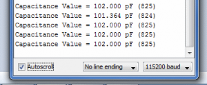
The code above loops round every half second, applying a 5V pulse to the capacitor, and measuring the voltage the other side. It then prints out the calculated capacitance (and raw ADC value).

If we try this out it won’t be very accurate. That is because the stray capacitance isn’t exactly 30pF. So we need to calibrate it. I did this with a 100pF capacitor. My multimeter reckons that it actually has a value of 102pF. The reading I get on my Arduino board is 125pF (raw ADC value 825). So if we put VA0 = 825, VA2 = 1023 and CT = 102 into the second equation, this tells us that C1 is 24.48pF. So I changed IN_STRAY_CAP_TO_GND to 24.48 and uploaded this to the Arduino. This time the value displayed on the serial monitor is 102pF (most of the time!).

CapTestSerialMon1

I tried it out with the following capacitors:

MiscCap1

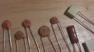
This was the results of my tests:

Capacitor Reading
0.072 pF (3)
15J 15.461 pF (396)
22J 23.403 pF (500)
47J 48.532 pF (680)
101J 102.000 pF (825)
471K 448.030 pF (970)
102K 1064.348 pF (1000)
392K 3553.097 pF (1016)
472K 4984.128 pF (1018)

I was curious to know how accurate this might be, so I worked it out. You can see the results of my analysis here. My conclusion was that you could expect a resolution of about 1% between 3.5pF and 225pF, and about 5% between 0.5pF and 1300pF. I haven’t worked the accuracy and linearity yet – I need to get hold of some very accurate reference capacitors (or a very accurate meter) for that.

You can build your own capacitor, and do experiments, which I have demonstrated here.

If you want to build on this or make a complete LCR meter, I have some ideas here.

Which micro-controller should you use?

Note: I may do a video to accompany this later. Let me know if that would be of interest…

A Short Introduction

Micro-controllers have been around a long time. Just recently though they have attracted a lot more interest, thanks mainly to the Arduino boards. People all over the world are now building  all sorts of exotic and innovative creations. If you are new to micro-controllers you would be well advised to start with an Arduino board (Arduino website).

Once you have played with this for a while you will probably be interested in getting some of the shields (plug in boards) that help out with tasks like driving motors (e.g. for robots) or LCD displays or connecting via wireless. USB or ethernet etc.

You will also discover that there are other boards available – using different processors. The ones that I’m going to mention here are the PIC based ones made by Digilent (chipKIT). These are the Uno32, uC32, DP32 and Max32. They are all based on the PIC32 chips. They run a lot faster than the Arduino boards (which are based on Atmel processors). Be warned though that you won’t be able to use the Arduino IDE – you have to use a specially adapted version called MPIDE. The idea is that you should be able to use sketches built for Arduino boards and recompile them without modification using MPIDE for the chipKIT boards. In practice, it’s not always as easy as that, so if you decide you want the faster speed and extra features, you may have to put up with having less support than you get with the Arduino boards.

There is another approach, which I am going to use – which is to use the PIC devices directly. Also, instead of using the MPIDE, I will be using Microchip’s IDE – MPLABX. Microchip provide three free compilers – XC8, XC16 and XC32 depending on whether you are programming an 8bit, 16bit or 32bit chip. They also provide an assember – MPASM if you need really feel the need to write the code directly in assembler!

You can use the chipKIT boards with MPLABX, but to be honest, if you are going down this route you might as well just program straight to the device itself. You’ll need a few external components, but you can build this all on a small breadboard, like this one:

Breadboard400

You will need to get a programmer / debugger, and the one that I would recommend is the PICkit 3. This connects your PC (Windows, MAC or linux) via USB, and to the board via a 6 pin header. This is obviously more effort that using the Arduino IDE or MPIDE, but there are several benefits to this extra effort:

  • Debugging (including breakpoints and register / variable inspection).
  • Ability to use a much wider range of devices.
  • Easier to understand hardware (most projects can be done with very few external components).

There are many other benefits – this is just some of them.

So if you’ve got here, you’re either an advanced user, or you’re felling brave and want to do some real hacking with real devices. If it’s the latter I applaud your ambition!

I will try to make this as painless as possible with the upcoming  tutorials. I am sure that you will find it much more satisfying than using a pre-built board.

Road Map

variousPICs

Welcome to my PIC tutorials. Over the coming weeks and months I plan to show some exciting ways to use the PIC micro-controllers. I’ll be working with devices from the PIC10 all the way up to the PIC32. Most of these devices are very inexpensive, but they really can do a LOT.

I’ll start by looking at what’s available, and then I’ll dive into programming some simple examples.

I’ll also occasionally include some articles about Arduino and chipKIT boards.