You can buy meters, like this one for instance:
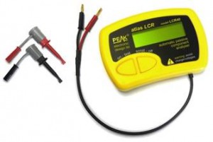
that measure capacitance, but where’s the fun in that?!
If you’ve got an Arduino, why not build one instead?
Note:
I've turned this into a library for the Arduino - so that's the easiest way to measure capacitance.
Search for "capacitor" in the Arduino IDE library manager (Tools menu, Manage Libraries...).
Update: Thank you for all the interest in this article! I have managed to increase the range, so it can measure capacitances of less than 1pF to over 1000uF , still with no external components! I’ve called this the Capacitance Meter Mk II.
There are lots of examples of how to do this on the internet, but I’m going to suggest an incredibly simple way to it. Let’s start with the theory.
Consider the following circuit:
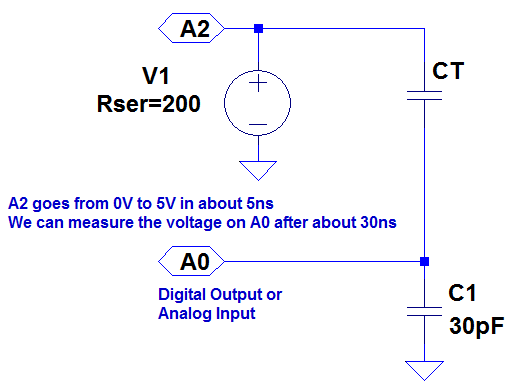
CT is the capacitor under test. We start with both capacitors discharged and A2 at 0 volts. When we raise A2 to 5 volts a current will flow through both capacitors. The voltage on A0 will settle to within 1% of it’s final value within 30ns. The value that A0 will settle to is proportional to the ratio of CT divided by the total capacitance, C1 + CT. The formulas that we are going to need are:
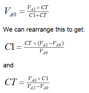
We will use the ADC to measure VA0. VA2 is actually 5 volts, so VA0 will vary from 0 to 5 volts, but we can use the ADC value instead, to make the calculations easier. Obviously we should then use the maximum ADC value (1023) for VA2. The ADC readings we can expect will range from about 33 for CT = 1pF to about 993 for CT = 1nF (1000pF).
So now we are ready to build the circuit and write the code. Right? Well, not quite. In the circuit above we have specified C1 as 30pF. But the Arduino will have some stray capacitance on the board and in the micro-controller. About 30pF of stray capacitance. We’re going to use this to make our circuit simpler – we are going to remove C1. But we need to work out how much stray capacitance there is, so we can plug it into the formulas above. But first, we’ll build the circuit and write the code.
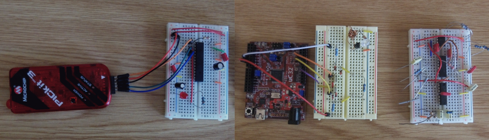
The circuit is surprisingly easy. In fact there isn’t a circuit now. We’re going to use the Arduino as follows:
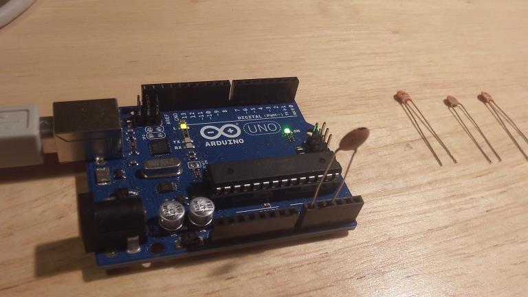
The capacitor is the capacitor under test between A0 and A2. The capacitors on the right are the capacitors that I am going to test a bit later on.
The code looks like this:
const int OUT_PIN = A2;
const int IN_PIN = A0;

//Capacitance between IN_PIN and Ground
//Stray capacitance is always present. Extra capacitance can be added to
//allow higher capacitance to be measured.
const float IN_STRAY_CAP_TO_GND = 24.48; //initially this was 30.00
const float IN_EXTRA_CAP_TO_GND = 0.0;
const float IN_CAP_TO_GND  = IN_STRAY_CAP_TO_GND + IN_EXTRA_CAP_TO_GND;
const int MAX_ADC_VALUE = 1023;

void setup()
{
  pinMode(OUT_PIN, OUTPUT);
  //digitalWrite(OUT_PIN, LOW);  //This is the default state for outputs
  pinMode(IN_PIN, OUTPUT);
  //digitalWrite(IN_PIN, LOW);

  Serial.begin(115200);
}

void loop()
{
  //Capacitor under test between OUT_PIN and IN_PIN
  //Rising high edge on OUT_PIN
  pinMode(IN_PIN, INPUT);
  digitalWrite(OUT_PIN, HIGH);
  int val = analogRead(IN_PIN);

  //Clear everything for next measurement
  digitalWrite(OUT_PIN, LOW);
  pinMode(IN_PIN, OUTPUT);

  //Calculate and print result

  float capacitance = (float)val * IN_CAP_TO_GND / (float)(MAX_ADC_VALUE - val);

  Serial.print(F("Capacitance Value = "));
  Serial.print(capacitance, 3);
  Serial.print(F(" pF ("));
  Serial.print(val);
  Serial.println(F(") "));

  while (millis() % 500 != 0)
    ;
}
The code above loops round every half second, applying a 5V pulse to the capacitor, and measuring the voltage the other side. It then prints out the calculated capacitance (and raw ADC value).
If we try this out it won’t be very accurate. That is because the stray capacitance isn’t exactly 30pF. So we need to calibrate it. I did this with a 100pF capacitor. My multimeter reckons that it actually has a value of 102pF. The reading I get on my Arduino board is 125pF (raw ADC value 825). So if we put VA0 = 825, VA2 = 1023 and CT = 102 into the second equation, this tells us that C1 is 24.48pF. So I changed IN_STRAY_CAP_TO_GND to 24.48 and uploaded this to the Arduino. This time the value displayed on the serial monitor is 102pF (most of the time!).

I tried it out with the following capacitors:

This was the results of my tests:
| Capacitor | Reading |
| – | 0.072 pF (3) |
| 15J | 15.461 pF (396) |
| 22J | 23.403 pF (500) |
| 47J | 48.532 pF (680) |
| 101J | 102.000 pF (825) |
| 471K | 448.030 pF (970) |
| 102K | 1064.348 pF (1000) |
| 392K | 3553.097 pF (1016) |
| 472K | 4984.128 pF (1018) |
I was curious to know how accurate this might be, so I worked it out. You can see the results of my analysis here. My conclusion was that you could expect a resolution of about 1% between 3.5pF and 225pF, and about 5% between 0.5pF and 1300pF. I haven’t worked the accuracy and linearity yet – I need to get hold of some very accurate reference capacitors (or a very accurate meter) for that.
You can build your own capacitor, and do experiments, which I have demonstrated here.
If you want to build on this or make a complete LCR meter, I have some ideas here.
Pingback: hackaday.com/2014/01/22/capacitance-measurement-with-the-arduino-uno
Pingback: 5jcodelabs.com/howtomrj/capacitance-measurement-with-the-arduino-uno
nice post
In the photo I can see you’re using USB power supply. With no doubt that accounts for the “error” in your measurements, since mostly never you’ll get the precise 5V reference on your USB port.
To compensate this you could use some software sorcery: https://code.google.com/p/tinkerit/wiki/SecretVoltmeter, or better the hardware hack – add MCP1541 to vRef, or some even more accurate (thus 10x more expensive) device, like LT1021.
I did personally added LT1021 (free samples available from linear.com) – now I can calibrate expensive voltmeters with my Arduino.
I don’t see anything in the code that assumes that MAX_ADC_VALUE corresponds to 5V. This code should work equally well over a range of +5V supply voltages, so long as the +5V supply is stable over the measurement period.
The program calculates a ratio not an absolute voltage so supply voltage shouldn’t matter.
Excellent idea and implementation. Will definitely give it a try. Keep up the good work
Great piece of work!! I will have to try this out at once.
Hey great job one problem, your “second equation” is incorrect, you meant to put Va0 in the denominator. Thanks for this!
Well spotted! I could say that was a “deliberate mistake” – but it wasn’t, it was just a mistake. Thanks again for spotting that.
in the void loop() i don’t understand the while(1) loop.
Why the while(1) loop?
You are absolutely correct. The while(1) loop is completely unnecessary since loop() will be called continuously – so I have removed it. Thanks.
Nice, simple and by that merit elegant, whats not to like – well done.
I am right in thinking there must be a limit to the largest capacitor you can measure. The maximum current these outputs can source is 20mA?
It shouldn’t matter how much current can be sourced (or the rise time) – the result should be the same. The only problem may be damaging the microcontroller, but it should be fine up to about 100uF. To be on the safe side you could include series resistors, but this might mean longer delays are required to reach a steady state.
A current-limiting resistor is a good idea. A cap looks like a dead short to ground when you first apply the 5V to it. Long term, this could damage an output pin. To limit 5V to 20mA requires a 250 Ohm resistor – make it 270 to be safe. An RC circuit will reach 90% of its final value in 2.2RC. So a 100pF capacitor in series with a 270 Ohm resistor will reach 4.5V in 59 nanoseconds. This can be a source of error as the cap being tested gets larger. One way to test these is to put them into an oscillator and measure the resulting frequency.
this was my thinking. say someone building a supercap project saw this and, without thought, just hooked it up straight as show – the cap will look like a dead S/C and would damage the arduino. Maybe and extension of this project could be employing some circuitry to accommodate large caps accurately? Or you done on this one Jon?
As long as the capacitor is discharged it should be ok… because we only apply a very short pulse (~100us – the time it takes to do the ADC conversion using analogRead()), and then discharge (which presumably would take another 100us). After that we wait ~499,800us before we have another go.
The only problem would be if someone hooked up a charged capacitor, but that could destroy the Arduino even if the I/O pins were set as inputs. I guess you could add an external resistor, but how big should that be? Someone could still hook up a capacitor charged up to hundreds of volts…
How to measure the power factor along with the capacitance. I have a very large capacitor. I don’t know its value. So I wanted to know the powerfactor so I can purchase in large.
Pingback: Arduino Uno rigged to measure capacitance | Bits & Pieces from the Embedded Design World
Great method! Seems to work very well. I made a capacitive water level sensor for my sump pump long ago but this is the first cap measuring application I have found that is stable enough to use. The water level sensor capacitance is between 40 and 450 pf, I added 100 pf to ground (IN_EXTRA_CAP_TO_GND) to make this app more accurate on the high end. added delay(1); right after the digitalWrite in the main loop to allow the measurement to settle, with these cap values it should settle in way less than 1 millisecond. Now if I can port it to a Tiny85 for low power… should work A2 is not used as an analog pin here, can use a digital pin, right?
Thank you. Yes, only IN_PIN (A0) is used as an analog input.
I have it working with a 2×16 LCD using an SPI backpack. Should now be portable to tiny85 is < 5k compiled and needs only five I/O pins. Very happy with your design.
Hello,
Looks interesting !!
Did you add additional Capacitor as reference as 100pf from Ao terminal to ground ??
Brilliant! Just brilliant! What a simple and elegant idea!
how big the capacitor can be? Can I measure electrolytic?
I have been working on an updated version of the code that will cover the range from 1nF up to over 1000uF using the internal pullup on one of the output pins. So altogether it will be able to measure capacitors from less than 1pF to over 1000uF (nine orders of magnitude). I’m quite pleased with the result. I’ll post that as another article on here today.
Nice job. I must be doing something entirely wrong though. When I upload the code and try to take a reading, I always get 1023 from A0 when a capacitor is hooked up and I get 0 to 3 when nothing is hooked up. There is no in between. I’m not sure what’s gone wrong.
I am trying this on MSP430g2252.
Draining a capacitor isn’t working:
I am putting a 100uF cap (charged to 3V) across 2 GPIO pins that are set to output LOW.
With a voltmeter, it is taking 30minutes to drain down to 0 V.
Any suggestions? Maybe msp430 can’t drain thru the IO pins?
I’m doing this for the LOW pins:
P1DIR |= pin;
P1SEL &= ~pin;
P1SEL2 &= ~pin;
P1OUT &= ~pin;
P1REN &= ~pin;
Any suggestions?
PS – I was also doing this, in addition to the above:
P1OUT &= ~pin;
Anyone else having luck draining a cap on msp430?
I figured it out. My analogRead was doing this:
ADC10AE0 = (1 << pin);
I put this in because I saw Energia used that. When I took this out, my capacitor drains quite quickly!
This is a great project! Isn't electronics fun?!
Nice post, i will try it myself in my arduino. Thank you for sharing it with us. Greetings from Argentina
Pingback: The Skinny: Balloons, Bikes, and Breathers | Skinny Research and Development
Pingback: Cum masori capacitatea unui condensator cu o placa Arduino | Robofun Blog
Hi, this is a great solution.
I’ve tried to measure my cap, which is about 30-50 pF with Arduino Due.
However, the measured value for the first run and loop are quite different.
In order to find the cause, I put the analogRead at A2 before A0 goes to HIGH.
And then I found the init value for first run and subsequent is different and seems like the discharge is not successful. Do you have any idea? Thank you!
Hi Guy, can I use this idea for pic16f 8bit, with adc 10bit and External OSC = 20MHz.
Thanks, Guy.
Hi there ,
For those who want to bring a serial lcd to make an autonomous device, I slightly modified the code as follow (you will need LiquidCrystal_V1.2.1 library)
#include // Comes with Arduino IDE
#include
LiquidCrystal_I2C lcd(0x27, 2, 1, 0, 4, 5, 6, 7, 3, POSITIVE); // Set the LCD I2C address
const int OUT_PIN = A2;
const int IN_PIN = A0;
//Capacitance between IN_PIN and Ground
//Stray capacitance value will vary from board to board.
//Calibrate this value using known capacitor.
const float IN_STRAY_CAP_TO_GND = 25;
const float IN_CAP_TO_GND = IN_STRAY_CAP_TO_GND;
//Pullup resistance will vary depending on board.
//Calibrate this with known capacitor.
const float R_PULLUP = 38.4; //in k ohms
const int MAX_ADC_VALUE = 1023;
void setup()
{
pinMode(OUT_PIN, OUTPUT);
//digitalWrite(OUT_PIN, LOW); //This is the default state for outputs
pinMode(IN_PIN, OUTPUT);
//digitalWrite(IN_PIN, LOW);
Serial.begin(115200);
lcd.begin(16,2);
}
void loop()
{
//Capacitor under test between OUT_PIN and IN_PIN
//Rising high edge on OUT_PIN
pinMode(IN_PIN, INPUT);
digitalWrite(OUT_PIN, HIGH);
int val = analogRead(IN_PIN);
digitalWrite(OUT_PIN, LOW);
if (val u1 ? u2 – u1 : u1 – u2;
} while ((digVal < 1) && (t 1000.0)
{
lcd.print(capacitance / 1000.0, 2);
lcd.print(F(” uF”));
}
else
{
lcd.print(capacitance, 2);
lcd.print(F(” nF”));
}
lcd.print(F(” (“));
lcd.println(F(“)”));
}
while (millis() % 1000 != 0)
;
}
Hey, you’ve done a great job with this, it’s going to be very useful for my project. But I have a hard time calibrating the MK II for capacitance < 1nF. I've tried the code on this article to figure it out but I get "Capacitance Value = inf pF (1023)".
I tried calibrating this on the other code but I don't get the correct value for capacitance under 1 nF. I'm working on 123d.circuits.io
Pingback: Мой дневник
Hello,
you have done a great job !!
This works for pF measurement but ,I would like to measure Capacitance of fF change …
Do anyone has done already this already ??
yep, very nice work, and yes the maximum sensitivity is when c(measure)=c(prob) by taking the first derivative dv/dc(t) which is the sensitivity (S) of the measurement and dS/dc(1) is a max when ct=c1.
Now S = V/2/C and since one click is about 1/1024 of V for the arduino, I get that one click is equal to about 0.2% of the capacitance (when ct=c1).
Sorry for this but very rarely do I get a chance to use my college calculus!!!!!
Its a similar calculation for measuring resistance.
anyway, back to work…….
Hi;
nice job. I was wondering if this method could be used for measuring the humidity of the soil???
Hi,
I found your article so useful and practical, it works like a charm.
just one thing:
changing the IN_STRAY_CAP_TO_GND does not affect the capacity calculation, so I can’t calibrate my device.
what should I do?