Further to the Arduino Capacitance Meter, if your feeling adventurous, or want to make a complete LCR meter I have a few more ideas…
Resistance Measurement
A similar circuit to the capacitance circuit could be used to measure resistance. Instead of a capacitor, use a resistor. Then the resistor under test and R1 form a potential divider. Like this:
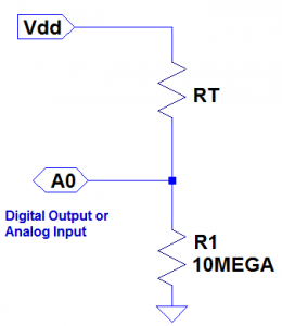
This time though, rather than applying a pulse, A0 should be pulled low to discharge any stray capacitance, and then changed to an input to read the voltage on R1. This should not be done immediately however, since any stray capacitance will delay the rising voltage. Assuming a capacitance of 50pF and a potential RT of 1000 M ohms, this time could be in the order of 250 ms. The code would look something like:
const int IN_PIN = A0;
const float R1 = 10.0;  //in M ohms

const int MAX_ADC_VALUE = 1023;

void setup()
{
  pinMode(IN_PIN, OUTPUT);
  //digitalWrite(IN_PIN, LOW);

  Serial.begin(115200);
}

void loop()
{
  while (1)
  {
    pinMode(IN_PIN, INPUT);
    delay(250);
    int val = analogRead(IN_PIN);

    //Clear everything for next measurement
    pinMode(IN_PIN, OUTPUT);

    //Calculate and print result

    float resistance = R1 * (float)(MAX_ADC_VALUE - val) / (float)val;

    Serial.print(F("Resistance Value = "));
    Serial.print(resistance, 3);
    Serial.print(F(" M ohms ("));
    Serial.print(val);
    Serial.println(F(") "));

    while (millis() % 500 != 0)
      ;
  }
}
This seems to work quite well from about 470KΩ to over 100MΩ. Above this the circuit seems to pick up a lot of stray noise and give increasingly inaccurate results. Care should also be taken not to let RT be too low as this may short the A0 pin to 5V while we try to discharge any stray capacitance. Unlike the capacitance meter, we are doing this for a relatively long time (250ms).
Inductance Measurement
Theoretically it should also be possible to measure inductance. A 10cm length of straight wire has an inductance of about 0.1uH. That would seem a good minimum amount of inductance to try and measure. The best that I can come up with is the following circuit:
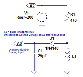
I have simulated this, and I think it should be able to measure inductances from about 1uH to 10mH with a resolution of about 5%. Since the 5V pulse is only 2us long we can probably don’t need R1 – in which case we only need one external component – D1.
Larger Capacitance Measurement
The code in the capacitance meter already has provision for measuring larger capacitors (which should be added from A0 to GND. A good value for the next range up would be 22nF. This will allow capacitors between about 1nF and 1uF to be measured. Because the 22nF capacitor needs longer to charge up, a delay of about 30us should be included before reading the ADC on A0. I have tried this and it does seem to work quite well.
It should also be possible to measure the next range – 1uF to 1000uF using a 22uF capacitor for C1. The delay to discharge C1 would now need to be about 30ms. When you measure capacitors of this size you need to make sure they are discharged first, otherwise you may damage the Arduino!
LCR Meter and Auto-ranging
If you want to get really fancy, you could combine all the ideas above. Changing range and mode could be achieved by connecting the extra R1 and C1 capacitors (and any inductors) to different I/O pins. Then you would enable features by changing the relevant I/O pin from an input (i.e. high impedance) to an output. The software should be able to take different measurements and work out the correct type and range.
Or you could just buy one… 😉
Hi,
I have a concern regarding your idea for an L meter above. While both capacitance and resistance allow for the use of a voltage divider when using DC steady state, for inductances, DC steady state will only measure the resistance of the inductor. This is because inductance only manifests itself when the current is changing. Also a current divider instead of a voltage divider would be needed and currents measured.
thank you!
You are absolutely right. I have been very vague about the inductance measurement, because I am not sure of a good way to do it. I have now included my best attempt, which involves using a diode, which I am not entirely happy about – but I think it should work, albeit with some non-linearity.
maybe something to try would be to generate an A/C signal of known frequency and measure voltage drops on the L – R voltage divider, then the inductance L would be R*V(on L)/2pi*f*V(on R), where f is the frequency, and Voltages measured over L and R.