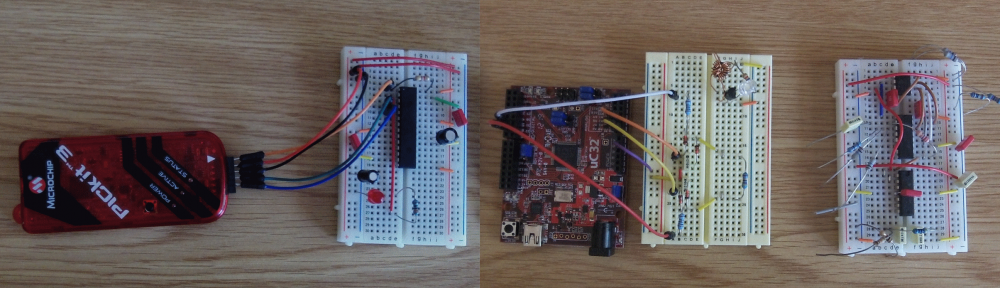
In order to test the nRF24L01 modules I created the following configurations:
- uC32 transmitter
- uC32 Receiver
- PIC16F1455 standalone board
I did the uC32 boards first because that was the easiest to develop. I am going to describe the standalone PIC16F1455 board first though, because that is the easiest to understand. It looks like this:
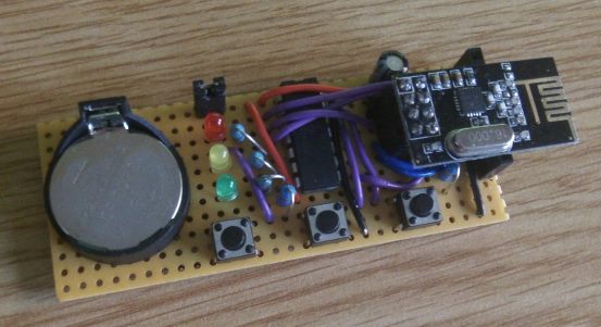
Note: I have created a PCB vesrion of this using OSH Park.
It consists of a PIC16F1455, 3 switches, 3 LEDs, a CR2032 battery to provide 3V, nRF24L01 connector and PICkit3 connector so we can program the PIC. It uses the PICs XLP mode and consumes about 10uA in standby mode – so the battery will last about 2 years. When any of the buttons are briefly pressed it will send a message (payload = ‘a’, ‘b’ or ‘c’), and then go into receive mode for 1 second, or until a message is received. If a message is received (‘a’, ‘b’ or ‘c’) one of the LEDs is lit for a second. If no message is received, after 1 second all the LEDs are briefly flashed. The board can be made to enter receive mode by pressing and holding the right hand switch for 5 seconds. Since receive mode consumes about 11mA we only stay in this mode for 1 minute. If we were to stay in this mode the battery would be drained in less than a day. I built this for my own use (I’m waiting for some PCBs from OSHPark), but if you would like to buy or make these yourself then let me know by emailing me at jon (at) codewrite (dot) co (dot) uk. To see a video of these boards in operation click here
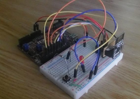
The uC32 board is connected up to the nRF24L01 using a 400 pin breadboard. There are two variations. One transmits a character and then waits for a reply. This looks like:
The other variant sits in receive mode and re-transmits every valid packet that it receives. That looks like this:
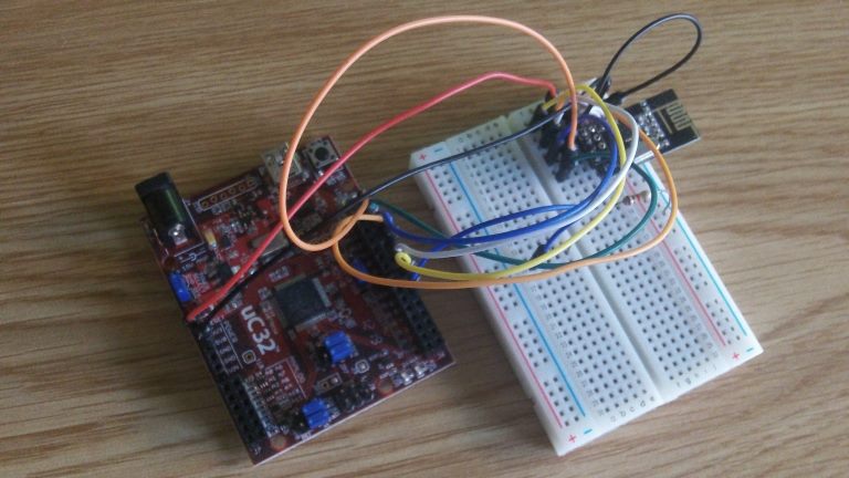
[By the way, the code for both variants is this same. One I/O pin is pulled either high or low. When the code starts it checks this input and runs either the transmit code or the receive code.]
In order to connect the nRF24L01 boards to the breadboard we need an adapter. This is because the 2×4 connector can’t be plugged straight into the breadboard (because of the breadboard’s terminal and bus strip arrangement). I tried two versions of this:
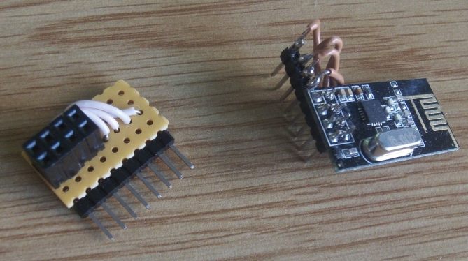
The one on the right was my first attempt which consisted of replacing the connector, whereas the one on the left is neater and doesn’t require the nRF24L01 board to be modified. Both can be plugged into the breadboard though.
Again, if you are interested in building one of these yourself, or buying an adapter, let me know at jon (at) codewrite (dot) co (dot) uk, and I’ll see what I can do. I might create a PCB adapter with switches and LEDs on it, so it can be plugged straight into the uC32 board, but that depends whether I can find the time to do it. Although the uC32 version is more expensive than the standalone PIC board (because we need the uC32 board) advantages of the uC32 version are:
- It’s easier to experiment with, using the serial library we can send messages to and from a PC or MAC.
- We can sit in receive mode indefinitely making range tests and debugging easier.
You can find the circuit diagram and code for these boards in the main article.
hi. I wanna make to boat with remote control by using nRF24L01. I wanna use to nRF24L01 module in transmitter and reciever. I have information about RF tranmistter and reciever but dont have nRF24L01. I will made transmitter and reciever with nRF24L01 by using PIC16f877A. I wander that how must be connection with nRF24L01 and PIC16f877A. that is, what is connection structure between its. Program Language that I will use is PIC BASIC PRO. Only I want to learn that Basicly I want to send any sort data from transmitter to recieve. I need to circuit diagraman and basic program for data commication. If I would have these infromation I can make boat with remote contol. thank you for you care in advance.
Thank you very much Mr.
Was the best example of functioning of nRF24L01, which I found on the internet.
The functions are very simple to interpret (simple).
I am now using these functions in my project.
I want to be a part of your group of friends.
Wilson.
Text translated from English (Brazil).