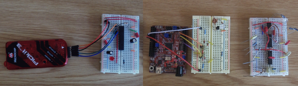
Building my nRF24L01 board on stripboard was quite time consuming, so I decided to design a PCB. Having looked into this, I decided that, for what I had in mind, there were two cost effective PCB manufacturers. These were:
- OSH Park and
- Seeed Studio
My board was going to be about one inch by two inches; OSH Park will make three boards for $15.50, and Seeed Studio will make five copies of the board for $18.90 (or ten boards for $23.90). Since this was a prototype, three boards was more than enough, so I went for OSH Park.
I used Eagle CAD to design the PCB. CadSoft have many variations of the Eagle product, but I went for the free version. This has some limitations, in that:
- You can’t use it commercially
- You can only make two-layer boards
- The board size is limited to 100mm x 80mm
You can still do a lot with the free version though – after all the Arduino board is only 70mm x 50mm!
The first stage was to enter the schematic. I had to create a couple of new components:
- CR2032 battery holder.
- 2×4 female header.
Curiously, Eagle CAD had a definition for a 2×5 female header, but not for a 2×4 version. I made a copy of the 2×5 version and turned into a 2×4 part.
The CR2032 holder was slightly more difficult, but again, I based this on a similar CR2032 holder that was in the existing library.
The schematic that ended up with looked like this:

You then click on the “Generate/switch to board” toolbar icon, which creates a new board layout. The components need to be dragged around to sensible places. Once you have done that you then run the autorouter tool. That does a pretty good job of routing the tracks. You can then change the widths of power lines etc. to get the layout that you want. I ended up with a layout that looked like this:
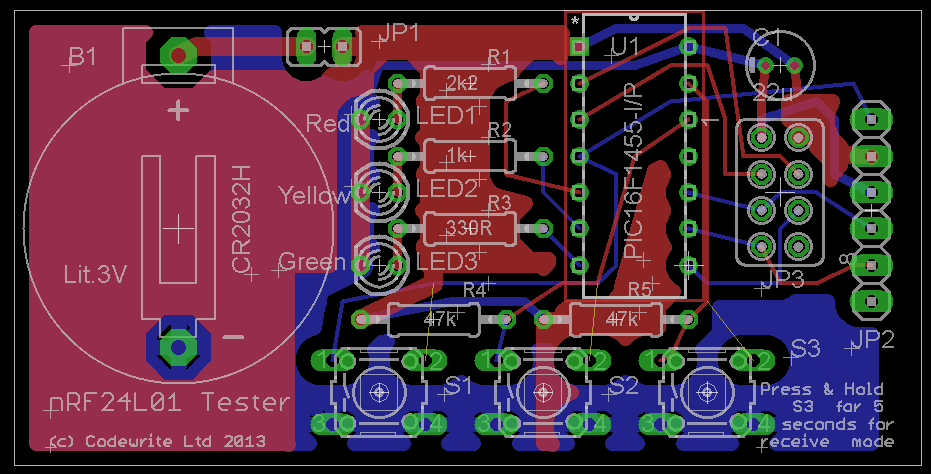
(actually it wasn’t quite like this, because the first version I did didn’t have the ground planes, which I’ve since decided would be a good idea :)).
Once you are happy with your design (and there are no errors) you have to upload it to the PCB manufacturers website. If you are using Seeed Studio you need to create a zip file with the gerber files in it. If you are using OSH Park you can upload the layout files directly. It’s a good idea to download their rules file to check that the board is going to be ok for them to manufacture.
So I did this on the 10 December last year, and paid my $15.50. They keep you very well informed about how your board is progressing, and I got my board on 2 Jan. Not too bad, considering that it was over the Christmas and New Year holidays; but it does show that you have to be a bit patient! The boards I got back looked like this:
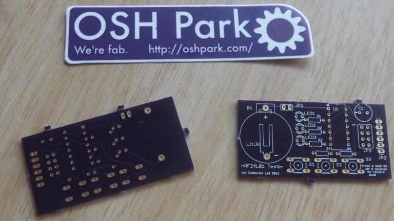
The only thing I had to do was file off the few bits of board that you can see poking out the side of the board. I then put all the components in and soldered them in place. The board then looked like this:
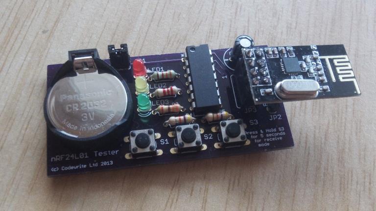
Much nicer looking than the stripboard version – it almost looks professional! 😉
The moment of truth was trying it out – and fortunately it worked first time. Yay!
Well I hope this article has been useful. If you have any questions you can contact me at jon (at) codewrite (dot) co (dot) uk. If you want to build these yourself, you can see my design at OSH Park. If you can’t be bothered to do that, but you really want the boards, then let me know and I’ll put them on ebay – I don’t know how much for – I’ll have to work out how much it cost me to buy all the bits, and how much it would cost to put in the post.