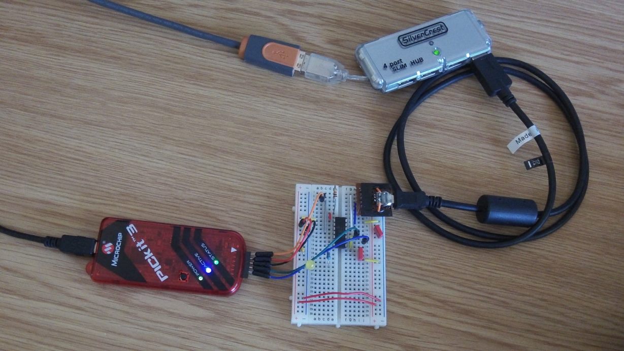
This time I am going to make a simple circuit using the PIC16F1455 and a mini USB connection. This will allow us to connect the PIC up to a PC (or any USB host) and communicate using a suitable device driver. I am going to use the serial class, so the PIC will appear as a serial port. This is a very cheap way to make a USB interface – I reckon all the parts (retail) would cost about £1.50 (~US $2).
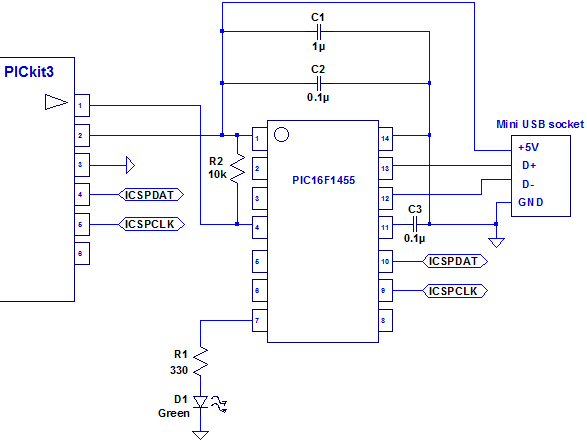
The schematic of this is:
In order to communicate via the PICs USB interface we need to get some code from Microchip. The code we need is the Microchip Libraries for Applications. I am using Windows 7, so I downloaded the Windows installer version. My advice is to install it to the default location, which for me was C:/microchip_solutions_v2013-02-15. If you like, you can try some of their examples, but they are all targeted at their development boards, so you will either need one of those, or you will need to modify the code a bit.
I am going to create a new project, and then add USB support to it. This is the same as before – create a standalone project, based on the 16F1455 using the PICkit3 and XC8. I have given it the rather unimaginative name USB_Blink3.
We need to add some include directories. We do this by right clicking the project and selecting properties. In the left hand window left click XC8 Compiler. In the right hand window click the “…” button on inlude directories. Add the follwing directories:
.

C:/microchip_solutions_v2013-02-15/Microchip/Include

C:/microchip_solutions_v2013-02-15/Microchip/Include/USB
The dot directory “.” will ensure that the microchip source files can find our local files.
We now need to add some files from the Microchip’s USB library. I have put these in a New Logical Folder called USB, located in the Source Files folder. The folder is created by right clicking on Source Files, and selecting New Logical Folder. This will create a folder which we then have to rename by right clicking it and selecting Rename.
The files that we need are located in:
C:/microchip_solutions_v2013-02-15/Microchip/USB/usb_device.c and

C:/microchip_solutions_v2013-02-15/Microchip/USB/CDC Device Driver/usb_function_cdc.c
We now need to create two new header files. These are HardwareProfile.h and usb_config.h. They should contain the following:
/*
 * File: HardwareProfile.h
 */

#ifndef HARDWAREPROFILE_H
#define HARDWAREPROFILE_H

#ifdef __cplusplus
extern "C" {
#endif

#define DEMO_BOARD USER_DEFINED_BOARD
#define USE_INTERNAL_OSC
#define tris_self_power TRISAbits.TRISA2 // Input
#define self_power 0

#define tris_usb_bus_sense TRISAbits.TRISA1 // Input
#define USB_BUS_SENSE 1

#ifdef __cplusplus
}
#endif

#endif /* HARDWAREPROFILE_H */
and
/*
 * File: usb_config.h
 */

#ifndef USB_CONFIG_H
#define USB_CONFIG_H

#ifdef __cplusplus
extern "C" {
#endif

#define USB_EP0_BUFF_SIZE 8 // Valid Options: 8, 16, 32, or 64 bytes.
#define USB_MAX_NUM_INT 1 // For tracking Alternate Setting

//Device descriptor - if these two definitions are not defined then
// a ROM USB_DEVICE_DESCRIPTOR variable by the exact name of device_dsc
// must exist.
#define USB_USER_DEVICE_DESCRIPTOR &device_dsc
#define USB_USER_DEVICE_DESCRIPTOR_INCLUDE extern ROM USB_DEVICE_DESCRIPTOR device_dsc

//Configuration descriptors - if these two definitions do not exist then
// a ROM BYTE *ROM variable named exactly USB_CD_Ptr[] must exist.
#define USB_USER_CONFIG_DESCRIPTOR USB_CD_Ptr
#define USB_USER_CONFIG_DESCRIPTOR_INCLUDE extern ROM BYTE *ROM USB_CD_Ptr[]

//Make sure only one of the below "#define USB_PING_PONG_MODE"
//is uncommented.
//#define USB_PING_PONG_MODE USB_PING_PONG__NO_PING_PONG
#define USB_PING_PONG_MODE USB_PING_PONG__FULL_PING_PONG
//#define USB_PING_PONG_MODE USB_PING_PONG__EP0_OUT_ONLY
//#define USB_PING_PONG_MODE USB_PING_PONG__ALL_BUT_EP0 //NOTE: This mode is not supported in PIC18F4550 family rev A3 devices

//#define USB_POLLING
#define USB_INTERRUPT

/* Parameter definitions are defined in usb_device.h */
#define USB_PULLUP_OPTION USB_PULLUP_ENABLE
//#define USB_PULLUP_OPTION USB_PULLUP_DISABLED

#define USB_TRANSCEIVER_OPTION USB_INTERNAL_TRANSCEIVER
//External Transceiver support is not available on all product families. Please
// refer to the product family datasheet for more information if this feature
// is available on the target processor.
//#define USB_TRANSCEIVER_OPTION USB_EXTERNAL_TRANSCEIVER

#define USB_SPEED_OPTION USB_FULL_SPEED
//#define USB_SPEED_OPTION USB_LOW_SPEED //(not valid option for PIC24F devices)

#define USB_SUPPORT_DEVICE

#define USB_NUM_STRING_DESCRIPTORS 3

//#define USB_INTERRUPT_LEGACY_CALLBACKS
#define USB_ENABLE_ALL_HANDLERS
//#define USB_ENABLE_SUSPEND_HANDLER
//#define USB_ENABLE_WAKEUP_FROM_SUSPEND_HANDLER
//#define USB_ENABLE_SOF_HANDLER
//#define USB_ENABLE_ERROR_HANDLER
//#define USB_ENABLE_OTHER_REQUEST_HANDLER
//#define USB_ENABLE_SET_DESCRIPTOR_HANDLER
//#define USB_ENABLE_INIT_EP_HANDLER
//#define USB_ENABLE_EP0_DATA_HANDLER
//#define USB_ENABLE_TRANSFER_COMPLETE_HANDLER

/** DEVICE CLASS USAGE *********************************************/
#define USB_USE_CDC

/** ENDPOINTS ALLOCATION *******************************************/
#define USB_MAX_EP_NUMBER 2

/* CDC */
#define CDC_COMM_INTF_ID 0x0
#define CDC_COMM_EP 1
#define CDC_COMM_IN_EP_SIZE 10

#define CDC_DATA_INTF_ID 0x01
#define CDC_DATA_EP 2
#define CDC_DATA_OUT_EP_SIZE 64
#define CDC_DATA_IN_EP_SIZE 64

//#define USB_CDC_SET_LINE_CODING_HANDLER mySetLineCodingHandler
//#define USB_CDC_SUPPORT_HARDWARE_FLOW_CONTROL

//#define USB_CDC_SUPPORT_ABSTRACT_CONTROL_MANAGEMENT_CAPABILITIES_D2 //Send_Break command
#define USB_CDC_SUPPORT_ABSTRACT_CONTROL_MANAGEMENT_CAPABILITIES_D1 //Set_Line_Coding, Set_Control_Line_State, Get_Line_Coding, and Serial_State commands
/** DEFINITIONS ****************************************************/

#ifdef __cplusplus
}
#endif

#endif /* USB_CONFIG_H */
Also, under Source Files, we need to create usb_descriptors.c and main.c. These should contain the following:
/*
 * File:   usb_descriptors.c

-usb_descriptors.c-
-------------------------------------------------------------------
Filling in the descriptor values in the usb_descriptors.c file:
-------------------------------------------------------------------

[Device Descriptors]
The device descriptor is defined as a USB_DEVICE_DESCRIPTOR type.
This type is defined in usb_ch9.h  Each entry into this structure
needs to be the correct length for the data type of the entry.

[Configuration Descriptors]
The configuration descriptor was changed in v2.x from a structure
to a BYTE array.  Given that the configuration is now a byte array
each byte of multi-byte fields must be listed individually.  This
means that for fields like the total size of the configuration where
the field is a 16-bit value "64,0," is the correct entry for a
configuration that is only 64 bytes long and not "64," which is one
too few bytes.

The configuration attribute must always have the _DEFAULT
definition at the minimum. Additional options can be ORed
to the _DEFAULT attribute. Available options are _SELF and _RWU.
These definitions are defined in the usb_device.h file. The
_SELF tells the USB host that this device is self-powered. The
_RWU tells the USB host that this device supports Remote Wakeup.

[Endpoint Descriptors]
Like the configuration descriptor, the endpoint descriptors were
changed in v2.x of the stack from a structure to a BYTE array.  As
endpoint descriptors also has a field that are multi-byte entities,
please be sure to specify both bytes of the field.  For example, for
the endpoint size an endpoint that is 64 bytes needs to have the size
defined as "64,0," instead of "64,"

Take the following example:
    // Endpoint Descriptor //
    0x07,                       //the size of this descriptor //
    USB_DESCRIPTOR_ENDPOINT,    //Endpoint Descriptor
    _EP02_IN,                   //EndpointAddress
    _INT,                       //Attributes
    0x08,0x00,                  //size (note: 2 bytes)
    0x02,                       //Interval

The first two parameters are self-explanatory. They specify the
length of this endpoint descriptor (7) and the descriptor type.
The next parameter identifies the endpoint, the definitions are
defined in usb_device.h and has the following naming
convention:
_EP<##>_<dir>
where ## is the endpoint number and dir is the direction of
transfer. The dir has the value of either 'OUT' or 'IN'.
The next parameter identifies the type of the endpoint. Available
options are _BULK, _INT, _ISO, and _CTRL. The _CTRL is not
typically used because the default control transfer endpoint is
not defined in the USB descriptors. When _ISO option is used,
addition options can be ORed to _ISO. Example:
_ISO|_AD|_FE
This describes the endpoint as an isochronous pipe with adaptive
and feedback attributes. See usb_device.h and the USB
specification for details. The next parameter defines the size of
the endpoint. The last parameter in the polling interval.

-------------------------------------------------------------------
Adding a USB String
-------------------------------------------------------------------
A string descriptor array should have the following format:

rom struct{byte bLength;byte bDscType;word string[size];}sdxxx={
sizeof(sdxxx),DSC_STR,<text>};

The above structure provides a means for the C compiler to
calculate the length of string descriptor sdxxx, where xxx is the
index number. The first two bytes of the descriptor are descriptor
length and type. The rest <text> are string texts which must be
in the unicode format. The unicode format is achieved by declaring
each character as a word type. The whole text string is declared
as a word array with the number of characters equals to <size>.
<size> has to be manually counted and entered into the array
declaration. Let's study this through an example:
if the string is "USB" , then the string descriptor should be:
(Using index 02)
rom struct{byte bLength;byte bDscType;word string[3];}sd002={
sizeof(sd002),DSC_STR,'U','S','B'};

A USB project may have multiple strings and the firmware supports
the management of multiple strings through a look-up table.
The look-up table is defined as:
rom const unsigned char *rom USB_SD_Ptr[]={&sd000,&sd001,&sd002};

The above declaration has 3 strings, sd000, sd001, and sd002.
Strings can be removed or added. sd000 is a specialized string
descriptor. It defines the language code, usually this is
US English (0x0409). The index of the string must match the index
position of the USB_SD_Ptr array, &sd000 must be in position
USB_SD_Ptr[0], &sd001 must be in position USB_SD_Ptr[1] and so on.
The look-up table USB_SD_Ptr is used by the get string handler
function.

-------------------------------------------------------------------

The look-up table scheme also applies to the configuration
descriptor. A USB device may have multiple configuration
descriptors, i.e. CFG01, CFG02, etc. To add a configuration
descriptor, user must implement a structure similar to CFG01.
The next step is to add the configuration descriptor name, i.e.
cfg01, cfg02,.., to the look-up table USB_CD_Ptr. USB_CD_Ptr[0]
is a dummy place holder since configuration 0 is the un-configured
state according to the definition in the USB specification.

********************************************************************/

/*********************************************************************
 * Descriptor specific type definitions are defined in:
 * usb_device.h
 *
 * Configuration options are defined in:
 * usb_config.h
 ********************************************************************/
#ifndef __USB_DESCRIPTORS_C
#define __USB_DESCRIPTORS_C

/** INCLUDES *******************************************************/
#include <usb.h>
#include <usb_function_cdc.h>

/** CONSTANTS ******************************************************/
#if defined(__18CXX)
#pragma romdata
#endif

/* Device Descriptor */
ROM USB_DEVICE_DESCRIPTOR device_dsc=
{
    0x12,                   // Size of this descriptor in bytes
    USB_DESCRIPTOR_DEVICE,  // DEVICE descriptor type
    0x0200,                 // USB Spec Release Number in BCD format
    CDC_DEVICE,             // Class Code
    0x00,                   // Subclass code
    0x00,                   // Protocol code
    USB_EP0_BUFF_SIZE,      // Max packet size for EP0, see usb_config.h
    0x04D8,                 // Vendor ID
    0x000A,                 // Product ID: CDC RS-232 Emulation Demo
    0x0100,                 // Device release number in BCD format
    0x01,                   // Manufacturer string index
    0x02,                   // Product string index
    0x00,                   // Device serial number string index
    0x01                    // Number of possible configurations
};

/* Configuration 1 Descriptor */
ROM BYTE configDescriptor1[]={
    /* Configuration Descriptor */
    0x09,//sizeof(USB_CFG_DSC),    // Size of this descriptor in bytes
    USB_DESCRIPTOR_CONFIGURATION,                // CONFIGURATION descriptor type
    67,0,                   // Total length of data for this cfg
    2,                      // Number of interfaces in this cfg
    1,                      // Index value of this configuration
    0,                      // Configuration string index
    _DEFAULT | _SELF,               // Attributes, see usb_device.h
    50,                     // Max power consumption (2X mA)

    /* Interface Descriptor */
    9,//sizeof(USB_INTF_DSC),   // Size of this descriptor in bytes
    USB_DESCRIPTOR_INTERFACE,               // INTERFACE descriptor type
    0,                      // Interface Number
    0,                      // Alternate Setting Number
    1,                      // Number of endpoints in this intf
    COMM_INTF,              // Class code
    ABSTRACT_CONTROL_MODEL, // Subclass code
    V25TER,                 // Protocol code
    0,                      // Interface string index

    /* CDC Class-Specific Descriptors */
    sizeof(USB_CDC_HEADER_FN_DSC),
    CS_INTERFACE,
    DSC_FN_HEADER,
    0x10,0x01,

    sizeof(USB_CDC_ACM_FN_DSC),
    CS_INTERFACE,
    DSC_FN_ACM,
    USB_CDC_ACM_FN_DSC_VAL,

    sizeof(USB_CDC_UNION_FN_DSC),
    CS_INTERFACE,
    DSC_FN_UNION,
    CDC_COMM_INTF_ID,
    CDC_DATA_INTF_ID,

    sizeof(USB_CDC_CALL_MGT_FN_DSC),
    CS_INTERFACE,
    DSC_FN_CALL_MGT,
    0x00,
    CDC_DATA_INTF_ID,

    /* Endpoint Descriptor */
    //sizeof(USB_EP_DSC),DSC_EP,_EP02_IN,_INT,CDC_INT_EP_SIZE,0x02,
    0x07,/*sizeof(USB_EP_DSC)*/
    USB_DESCRIPTOR_ENDPOINT,    //Endpoint Descriptor
    _EP01_IN,            //EndpointAddress
    _INTERRUPT,                       //Attributes
    0x08,0x00,                  //size
    0x02,                       //Interval

    /* Interface Descriptor */
    9,//sizeof(USB_INTF_DSC),   // Size of this descriptor in bytes
    USB_DESCRIPTOR_INTERFACE,               // INTERFACE descriptor type
    1,                      // Interface Number
    0,                      // Alternate Setting Number
    2,                      // Number of endpoints in this intf
    DATA_INTF,              // Class code
    0,                      // Subclass code
    NO_PROTOCOL,            // Protocol code
    0,                      // Interface string index

    /* Endpoint Descriptor */
    //sizeof(USB_EP_DSC),DSC_EP,_EP03_OUT,_BULK,CDC_BULK_OUT_EP_SIZE,0x00,
    0x07,/*sizeof(USB_EP_DSC)*/
    USB_DESCRIPTOR_ENDPOINT,    //Endpoint Descriptor
    _EP02_OUT,            //EndpointAddress
    _BULK,                       //Attributes
    0x40,0x00,                  //size
    0x00,                       //Interval

    /* Endpoint Descriptor */
    //sizeof(USB_EP_DSC),DSC_EP,_EP03_IN,_BULK,CDC_BULK_IN_EP_SIZE,0x00
    0x07,/*sizeof(USB_EP_DSC)*/
    USB_DESCRIPTOR_ENDPOINT,    //Endpoint Descriptor
    _EP02_IN,            //EndpointAddress
    _BULK,                       //Attributes
    0x40,0x00,                  //size
    0x00,                       //Interval
};

//Language code string descriptor
ROM struct{BYTE bLength;BYTE bDscType;WORD string[1];}sd000={
sizeof(sd000),USB_DESCRIPTOR_STRING,{0x0409}};

//Manufacturer string descriptor
ROM struct{BYTE bLength;BYTE bDscType;WORD string[25];}sd001={
sizeof(sd001),USB_DESCRIPTOR_STRING,
{'M','i','c','r','o','c','h','i','p',' ',
'T','e','c','h','n','o','l','o','g','y',' ','I','n','c','.'
}};

//Product string descriptor
ROM struct{BYTE bLength;BYTE bDscType;WORD string[25];}sd002={
sizeof(sd002),USB_DESCRIPTOR_STRING,
{'C','D','C',' ','R','S','-','2','3','2',' ',
'E','m','u','l','a','t','i','o','n',' ','D','e','m','o'}
};

//Array of configuration descriptors
ROM BYTE *ROM USB_CD_Ptr[]=
{
    (ROM BYTE *ROM)&configDescriptor1
};
//Array of string descriptors
ROM BYTE *ROM USB_SD_Ptr[USB_NUM_STRING_DESCRIPTORS]=
{
    (ROM BYTE *ROM)&sd000,
    (ROM BYTE *ROM)&sd001,
    (ROM BYTE *ROM)&sd002
};

#if defined(__18CXX)
    #pragma code
#endif

#endif
/** EOF usb_descriptors.c ****************************************************/
/*
* File: main.c
*/
#include <stdio.h>
#include <stdlib.hgt;
#include <usb.hgt;
#include <usb_function_cdc.hgt;
#include "HardwareProfile.h"
// CONFIG1
#pragma config FOSC = INTOSC // Oscillator Selection Bits (INTOSC oscillator: I/O function on CLKIN pin)
#pragma config WDTE = OFF // Watchdog Timer Enable (WDT disabled)
#pragma config PWRTE = OFF // Power-up Timer Enable (PWRT disabled)
#pragma config MCLRE = ON // MCLR Pin Function Select (MCLR/VPP pin function is MCLR)
#pragma config CP = OFF // Flash Program Memory Code Protection (Program memory code protection is disabled)
#pragma config BOREN = ON // Brown-out Reset Enable (Brown-out Reset enabled)
#pragma config CLKOUTEN = OFF // Clock Out Enable (CLKOUT function is disabled. I/O or oscillator function on the CLKOUT pin)
#pragma config IESO = OFF // Internal/External Switchover Mode (Internal/External Switchover Mode is enabled)
#pragma config FCMEN = OFF // Fail-Safe Clock Monitor Enable (Fail-Safe Clock Monitor is enabled)
// CONFIG2
#pragma config WRT = OFF // Flash Memory Self-Write Protection (Write protection off)
#pragma config CPUDIV = NOCLKDIV // CPU System Clock Selection Bit (CPU system clock divided by 6)
#pragma config USBLSCLK = 48MHz // USB Low SPeed Clock Selection bit (System clock expects 48 MHz, FS/LS USB CLKENs divide-by is set to 8.)
#pragma config PLLMULT = 3x // PLL Multipler Selection Bit (3x Output Frequency Selected)
#pragma config PLLEN = ENABLED // PLL Enable Bit (3x or 4x PLL Enabled)
#pragma config STVREN = ON // Stack Overflow/Underflow Reset Enable (Stack Overflow or Underflow will cause a Reset)
#pragma config BORV = LO // Brown-out Reset Voltage Selection (Brown-out Reset Voltage (Vbor), low trip point selected.)
#pragma config LPBOR = OFF // Low-Power Brown Out Reset (Low-Power BOR is disabled)
#pragma config LVP = OFF // Low-Voltage Programming Enable (Low-voltage programming enabled)
/** V A R I A B L E S ********************************************************/
char USB_In_Buffer[64];
char USB_Out_Buffer[64];
int tmrCounter = 0;
int tmrMask = 0x7FF;
int tmrVal = 0x400;
/** P R I V A T E P R O T O T Y P E S ***************************************/
static void InitializeSystem(void);
void ProcessIO(void);
void USBDeviceTasks(void);
void YourHighPriorityISRCode();
void YourLowPriorityISRCode();
void USBCBSendResume(void);
void BlinkUSBStatus(void);
void UserInit(void);
/** VECTOR REMAPPING ***********************************************/
//These are your actual interrupt handling routines.
void interrupt ISRCode()
{
//Check which interrupt flag caused the interrupt.
//Service the interrupt
//Clear the interrupt flag
//Etc.
#if defined(USB_INTERRUPT)
if (USBInterruptFlag != 0)
USBDeviceTasks();
#endif
if (INTCONbits.TMR0IF)
{
tmrCounter++;
if ((tmrCounter & tmrMask) == tmrVal)
RC3 = 1;
if ((tmrCounter & tmrMask) == 0x0000)
RC3 = 0;
INTCONbits.TMR0IF = 0;
}
}
/** DECLARATIONS ***************************************************/
#if defined(__18CXX)
#pragma code
#endif
/******************************************************************************
* Function: void main(void)
*
* PreCondition: None
*
* Input: None
*
* Output: None
*
* Side Effects: None
*
* Overview: Main program entry point.
*
* Note: None
*****************************************************************************/
int main(void)
{
InitializeSystem();
while(1)
{
#if defined(USB_INTERRUPT)
if(USB_BUS_SENSE && (USBGetDeviceState() == DETACHED_STATE))
{
USBDeviceAttach();
}
#endif
#if defined(USB_POLLING)
// Check bus status and service USB interrupts.
USBDeviceTasks(); // Interrupt or polling method. If using polling, must call
// this function periodically. This function will take care
// of processing and responding to SETUP transactions
// (such as during the enumeration process when you first
// plug in). USB hosts require that USB devices should accept
// and process SETUP packets in a timely fashion. Therefore,
// when using polling, this function should be called
// regularly (such as once every 1.8ms or faster** [see
// inline code comments in usb_device.c for explanation when
// "or faster" applies]) In most cases, the USBDeviceTasks()
// function does not take very long to execute (ex: <100
// instruction cycles) before it returns.
#endif
// Application-specific tasks.
// Application related code may be added here, or in the ProcessIO() function.
ProcessIO();
}//end while
}//end main
/********************************************************************
* Function: static void InitializeSystem(void)
*
* PreCondition: None
*
* Input: None
*
* Output: None
*
* Side Effects: None
*
* Overview: InitializeSystem is a centralize initialization
* routine. All required USB initialization routines
* are called from here.
*
* User application initialization routine should
* also be called from here.
*
* Note: None
*******************************************************************/
static void InitializeSystem(void)
{
#if defined(_PIC14E)
//Configure all pins for digital mode
ANSELA = 0x00;
ANSELC = 0x00;
#if defined (USE_INTERNAL_OSC)
OSCTUNE = 0;
OSCCON = 0xFC; //16MHz HFINTOSC with 3x PLL enabled (48MHz operation)
ACTCON = 0x90; //Enable active clock tuning with USB
#endif
#endif
// The USB specifications require that USB peripheral devices must never source
// current onto the Vbus pin. Additionally, USB peripherals should not source
// current on D+ or D- when the host/hub is not actively powering the Vbus line.
// When designing a self powered (as opposed to bus powered) USB peripheral
// device, the firmware should make sure not to turn on the USB module and D+
// or D- pull up resistor unless Vbus is actively powered. Therefore, the
// firmware needs some means to detect when Vbus is being powered by the host.
// A 5V tolerant I/O pin can be connected to Vbus (through a resistor), and
// can be used to detect when Vbus is high (host actively powering), or low
// (host is shut down or otherwise not supplying power). The USB firmware
// can then periodically poll this I/O pin to know when it is okay to turn on
// the USB module/D+/D- pull up resistor. When designing a purely bus powered
// peripheral device, it is not possible to source current on D+ or D- when the
// host is not actively providing power on Vbus. Therefore, implementing this
// bus sense feature is optional. This firmware can be made to use this bus
// sense feature by making sure "USE_USB_BUS_SENSE_IO" has been defined in the
// HardwareProfile.h file.
#if defined(USE_USB_BUS_SENSE_IO)
tris_usb_bus_sense = INPUT_PIN; // See HardwareProfile.h
#endif
// If the host PC sends a GetStatus (device) request, the firmware must respond
// and let the host know if the USB peripheral device is currently bus powered
// or self powered. See chapter 9 in the official USB specifications for details
// regarding this request. If the peripheral device is capable of being both
// self and bus powered, it should not return a hard coded value for this request.
// Instead, firmware should check if it is currently self or bus powered, and
// respond accordingly. If the hardware has been configured like demonstrated
// on the PICDEM FS USB Demo Board, an I/O pin can be polled to determine the
// currently selected power source. On the PICDEM FS USB Demo Board, "RA2"
// is used for this purpose. If using this feature, make sure "USE_SELF_POWER_SENSE_IO"
// has been defined in HardwareProfile - (platform).h, and that an appropriate I/O pin
// has been mapped to it.
#if defined(USE_SELF_POWER_SENSE_IO)
tris_self_power = INPUT_PIN; // See HardwareProfile.h
#endif
UserInit();
USBDeviceInit(); //usb_device.c. Initializes USB module SFRs and firmware
//variables to known states.
}//end InitializeSystem
/******************************************************************************
* Function: void UserInit(void)
*
* PreCondition: None
*
* Input: None
*
* Output: None
*
* Side Effects: None
*
* Overview: This routine should take care of all of the demo code
* initialization that is required.
*
* Note:
*
*****************************************************************************/
void UserInit(void)
{
TRISC = 0xF7; //Set RC3 as output
OPTION_REG = 0xC3; //Set prescaler to 256
TMR0 = 0xFF; //Timer0 module register
INTCONbits.TMR0IF = 0;
INTCONbits.TMR0IE = 1;
}//end UserInit
/********************************************************************
* Function: void ProcessIO(void)
*
* PreCondition: None
*
* Input: None
*
* Output: None
*
* Side Effects: None
*
* Overview: This function is a place holder for other user
* routines. It is a mixture of both USB and
* non-USB tasks.
*
* Note: None
*******************************************************************/
void ProcessIO(void)
{
BYTE numBytesRead;
//Blink the LEDs according to the USB device status
BlinkUSBStatus();
// User Application USB tasks
if((USBDeviceState < CONFIGURED_STATE)||(USBSuspendControl==1)) return;
if(USBUSARTIsTxTrfReady())
{
numBytesRead = getsUSBUSART(USB_Out_Buffer,64);
if(numBytesRead != 0)
{
BYTE i;
BOOL validCmd = TRUE;
for(i=0;i<numBytesRead;i++)
{
switch(USB_Out_Buffer[i])
{
case '1':
tmrMask = 0xFFF;
tmrVal = 0x800;
break;
case '2':
tmrMask = 0x7FF;
tmrVal = 0x400;
break;
case '3':
tmrMask = 0x3FF;
tmrVal = 0x200;
break;
case '4':
tmrMask = 0x1FF;
tmrVal = 0x100;
break;
default:
validCmd = FALSE;
break;
}
}
if (validCmd)
putUSBUSART((char*)"Done ",5);
else
putUSBUSART((char*)"Invalid Command ",16);
}
}
CDCTxService();
} //end ProcessIO
/********************************************************************
* Function: void BlinkUSBStatus(void)
*
* PreCondition: None
*
* Input: None
*
* Output: None
*
* Side Effects: None
*
* Overview: BlinkUSBStatus turns on and off LEDs
* corresponding to the USB device state.
*
* Note: mLED macros can be found in HardwareProfile.h
* USBDeviceState is declared and updated in
* usb_device.c.
*******************************************************************/
void BlinkUSBStatus(void)
{
if(USBSuspendControl == 1)
{
}
else
{
if(USBDeviceState == DETACHED_STATE)
{
}
else if(USBDeviceState == ATTACHED_STATE)
{
}
else if(USBDeviceState == POWERED_STATE)
{
}
else if(USBDeviceState == DEFAULT_STATE)
{
}
else if(USBDeviceState == ADDRESS_STATE)
{
}
else if(USBDeviceState == CONFIGURED_STATE)
{
}//end if(...)
}//end if(UCONbits.SUSPND...)
}//end BlinkUSBStatus
// ******************************************************************************************************
// ************** USB Callback Functions ****************************************************************
// ******************************************************************************************************
// The USB firmware stack will call the callback functions USBCBxxx() in response to certain USB related
// events. For example, if the host PC is powering down, it will stop sending out Start of Frame (SOF)
// packets to your device. In response to this, all USB devices are supposed to decrease their power
// consumption from the USB Vbus to <2.5mA* each. The USB module detects this condition (which according
// to the USB specifications is 3+ms of no bus activity/SOF packets) and then calls the USBCBSuspend()
// function. You should modify these callback functions to take appropriate actions for each of these
// conditions. For example, in the USBCBSuspend(), you may wish to add code that will decrease power
// consumption from Vbus to <2.5mA (such as by clock switching, turning off LEDs, putting the
// microcontroller to sleep, etc.). Then, in the USBCBWakeFromSuspend() function, you may then wish to
// add code that undoes the power saving things done in the USBCBSuspend() function.
// The USBCBSendResume() function is special, in that the USB stack will not automatically call this
// function. This function is meant to be called from the application firmware instead. See the
// additional comments near the function.
// Note *: The "usb_20.pdf" specs indicate 500uA or 2.5mA, depending upon device classification. However,
// the USB-IF has officially issued an ECN (engineering change notice) changing this to 2.5mA for all
// devices. Make sure to re-download the latest specifications to get all of the newest ECNs.
/******************************************************************************
* Function: void USBCBSuspend(void)
*
* PreCondition: None
*
* Input: None
*
* Output: None
*
* Side Effects: None
*
* Overview: Call back that is invoked when a USB suspend is detected
*
* Note: None
*****************************************************************************/
void USBCBSuspend(void)
{
//Example power saving code. Insert appropriate code here for the desired
//application behavior. If the microcontroller will be put to sleep, a
//process similar to that shown below may be used:
//ConfigureIOPinsForLowPower();
//SaveStateOfAllInterruptEnableBits();
//DisableAllInterruptEnableBits();
//EnableOnlyTheInterruptsWhichWillBeUsedToWakeTheMicro(); //should enable at least USBActivityIF as a wake source
//Sleep();
//RestoreStateOfAllPreviouslySavedInterruptEnableBits(); //Preferrably, this should be done in the USBCBWakeFromSuspend() function instead.
//RestoreIOPinsToNormal(); //Preferrably, this should be done in the USBCBWakeFromSuspend() function instead.
//IMPORTANT NOTE: Do not clear the USBActivityIF (ACTVIF) bit here. This bit is
//cleared inside the usb_device.c file. Clearing USBActivityIF here will cause
//things to not work as intended.
#if defined(__C30__) || defined __XC16__
USBSleepOnSuspend();
#endif
}
/******************************************************************************
* Function: void USBCBWakeFromSuspend(void)
*
* PreCondition: None
*
* Input: None
*
* Output: None
*
* Side Effects: None
*
* Overview: The host may put USB peripheral devices in low power
* suspend mode (by "sending" 3+ms of idle). Once in suspend
* mode, the host may wake the device back up by sending non-
* idle state signalling.
*
* This call back is invoked when a wakeup from USB suspend
* is detected.
*
* Note: None
*****************************************************************************/
void USBCBWakeFromSuspend(void)
{
// If clock switching or other power savings measures were taken when
// executing the USBCBSuspend() function, now would be a good time to
// switch back to normal full power run mode conditions. The host allows
// 10+ milliseconds of wakeup time, after which the device must be
// fully back to normal, and capable of receiving and processing USB
// packets. In order to do this, the USB module must receive proper
// clocking (IE: 48MHz clock must be available to SIE for full speed USB
// operation).
// Make sure the selected oscillator settings are consistent with USB
// operation before returning from this function.
}
/********************************************************************
* Function: void USBCB_SOF_Handler(void)
*
* PreCondition: None
*
* Input: None
*
* Output: None
*
* Side Effects: None
*
* Overview: The USB host sends out a SOF packet to full-speed
* devices every 1 ms. This interrupt may be useful
* for isochronous pipes. End designers should
* implement callback routine as necessary.
*
* Note: None
*******************************************************************/
void USBCB_SOF_Handler(void)
{
// No need to clear UIRbits.SOFIF to 0 here.
// Callback caller is already doing that.
}
/*******************************************************************
* Function: void USBCBErrorHandler(void)
*
* PreCondition: None
*
* Input: None
*
* Output: None
*
* Side Effects: None
*
* Overview: The purpose of this callback is mainly for
* debugging during development. Check UEIR to see
* which error causes the interrupt.
*
* Note: None
*******************************************************************/
void USBCBErrorHandler(void)
{
// No need to clear UEIR to 0 here.
// Callback caller is already doing that.
// Typically, user firmware does not need to do anything special
// if a USB error occurs. For example, if the host sends an OUT
// packet to your device, but the packet gets corrupted (ex:
// because of a bad connection, or the user unplugs the
// USB cable during the transmission) this will typically set
// one or more USB error interrupt flags. Nothing specific
// needs to be done however, since the SIE will automatically
// send a "NAK" packet to the host. In response to this, the
// host will normally retry to send the packet again, and no
// data loss occurs. The system will typically recover
// automatically, without the need for application firmware
// intervention.
// Nevertheless, this callback function is provided, such as
// for debugging purposes.
}
/*******************************************************************
* Function: void USBCBCheckOtherReq(void)
*
* PreCondition: None
*
* Input: None
*
* Output: None
*
* Side Effects: None
*
* Overview: When SETUP packets arrive from the host, some
* firmware must process the request and respond
* appropriately to fulfill the request. Some of
* the SETUP packets will be for standard
* USB "chapter 9" (as in, fulfilling chapter 9 of
* the official USB specifications) requests, while
* others may be specific to the USB device class
* that is being implemented. For example, a HID
* class device needs to be able to respond to
* "GET REPORT" type of requests. This
* is not a standard USB chapter 9 request, and
* therefore not handled by usb_device.c. Instead
* this request should be handled by class specific
* firmware, such as that contained in usb_function_hid.c.
*
* Note: None
*******************************************************************/
void USBCBCheckOtherReq(void)
{
USBCheckCDCRequest();
}//end
/*******************************************************************
* Function: void USBCBStdSetDscHandler(void)
*
* PreCondition: None
*
* Input: None
*
* Output: None
*
* Side Effects: None
*
* Overview: The USBCBStdSetDscHandler() callback function is
* called when a SETUP, bRequest: SET_DESCRIPTOR request
* arrives. Typically SET_DESCRIPTOR requests are
* not used in most applications, and it is
* optional to support this type of request.
*
* Note: None
*******************************************************************/
void USBCBStdSetDscHandler(void)
{
// Must claim session ownership if supporting this request
}//end
/*******************************************************************
* Function: void USBCBInitEP(void)
*
* PreCondition: None
*
* Input: None
*
* Output: None
*
* Side Effects: None
*
* Overview: This function is called when the device becomes
* initialized, which occurs after the host sends a
* SET_CONFIGURATION (wValue not = 0) request. This
* callback function should initialize the endpoints
* for the device's usage according to the current
* configuration.
*
* Note: None
*******************************************************************/
void USBCBInitEP(void)
{
//Enable the CDC data endpoints
CDCInitEP();
}
/********************************************************************
* Function: void USBCBSendResume(void)
*
* PreCondition: None
*
* Input: None
*
* Output: None
*
* Side Effects: None
*
* Overview: The USB specifications allow some types of USB
* peripheral devices to wake up a host PC (such
* as if it is in a low power suspend to RAM state).
* This can be a very useful feature in some
* USB applications, such as an Infrared remote
* control receiver. If a user presses the "power"
* button on a remote control, it is nice that the
* IR receiver can detect this signalling, and then
* send a USB "command" to the PC to wake up.
*
* The USBCBSendResume() "callback" function is used
* to send this special USB signalling which wakes
* up the PC. This function may be called by
* application firmware to wake up the PC. This
* function will only be able to wake up the host if
* all of the below are true:
*
* 1. The USB driver used on the host PC supports
* the remote wakeup capability.
* 2. The USB configuration descriptor indicates
* the device is remote wakeup capable in the
* bmAttributes field.
* 3. The USB host PC is currently sleeping,
* and has previously sent your device a SET
* FEATURE setup packet which "armed" the
* remote wakeup capability.
*
* If the host has not armed the device to perform remote wakeup,
* then this function will return without actually performing a
* remote wakeup sequence. This is the required behavior,
* as a USB device that has not been armed to perform remote
* wakeup must not drive remote wakeup signalling onto the bus;
* doing so will cause USB compliance testing failure.
*
* This callback should send a RESUME signal that
* has the period of 1-15ms.
*
* Note: This function does nothing and returns quickly, if the USB
* bus and host are not in a suspended condition, or are
* otherwise not in a remote wakeup ready state. Therefore, it
* is safe to optionally call this function regularly, ex:
* anytime application stimulus occurs, as the function will
* have no effect, until the bus really is in a state ready
* to accept remote wakeup.
*
* When this function executes, it may perform clock switching,
* depending upon the application specific code in
* USBCBWakeFromSuspend(). This is needed, since the USB
* bus will no longer be suspended by the time this function
* returns. Therefore, the USB module will need to be ready
* to receive traffic from the host.
*
* The modifiable section in this routine may be changed
* to meet the application needs. Current implementation
* temporary blocks other functions from executing for a
* period of ~3-15 ms depending on the core frequency.
*
* According to USB 2.0 specification section 7.1.7.7,
* "The remote wakeup device must hold the resume signaling
* for at least 1 ms but for no more than 15 ms."
* The idea here is to use a delay counter loop, using a
* common value that would work over a wide range of core
* frequencies.
* That value selected is 1800. See table below:
* ==========================================================
* Core Freq(MHz) MIP RESUME Signal Period (ms)
* ==========================================================
* 48 12 1.05
* 4 1 12.6
* ==========================================================
* * These timing could be incorrect when using code
* optimization or extended instruction mode,
* or when having other interrupts enabled.
* Make sure to verify using the MPLAB SIM's Stopwatch
* and verify the actual signal on an oscilloscope.
*******************************************************************/
void USBCBSendResume(void)
{
static WORD delay_count;
//First verify that the host has armed us to perform remote wakeup.
//It does this by sending a SET_FEATURE request to enable remote wakeup,
//usually just before the host goes to standby mode (note: it will only
//send this SET_FEATURE request if the configuration descriptor declares
//the device as remote wakeup capable, AND, if the feature is enabled
//on the host (ex: on Windows based hosts, in the device manager
//properties page for the USB device, power management tab, the
//"Allow this device to bring the computer out of standby." checkbox
//should be checked).
if(USBGetRemoteWakeupStatus() == TRUE)
{
//Verify that the USB bus is in fact suspended, before we send
//remote wakeup signalling.
if(USBIsBusSuspended() == TRUE)
{
USBMaskInterrupts();
//Clock switch to settings consistent with normal USB operation.
USBCBWakeFromSuspend();
USBSuspendControl = 0;
USBBusIsSuspended = FALSE; //So we don't execute this code again,
//until a new suspend condition is detected.
//Section 7.1.7.7 of the USB 2.0 specifications indicates a USB
//device must continuously see 5ms+ of idle on the bus, before it sends
//remote wakeup signalling. One way to be certain that this parameter
//gets met, is to add a 2ms+ blocking delay here (2ms plus at
//least 3ms from bus idle to USBIsBusSuspended() == TRUE, yeilds
//5ms+ total delay since start of idle).
delay_count = 3600U;
do
{
delay_count--;
}while(delay_count);
//Now drive the resume K-state signalling onto the USB bus.
USBResumeControl = 1; // Start RESUME signaling
delay_count = 1800U; // Set RESUME line for 1-13 ms
do
{
delay_count--;
}while(delay_count);
USBResumeControl = 0; //Finished driving resume signalling
USBUnmaskInterrupts();
}
}
}
/*******************************************************************
* Function: void USBCBEP0DataReceived(void)
*
* PreCondition: ENABLE_EP0_DATA_RECEIVED_CALLBACK must be
* defined already (in usb_config.h)
*
* Input: None
*
* Output: None
*
* Side Effects: None
*
* Overview: This function is called whenever a EP0 data
* packet is received. This gives the user (and
* thus the various class examples a way to get
* data that is received via the control endpoint.
* This function needs to be used in conjunction
* with the USBCBCheckOtherReq() function since
* the USBCBCheckOtherReq() function is the apps
* method for getting the initial control transfer
* before the data arrives.
*
* Note: None
*******************************************************************/
#if defined(ENABLE_EP0_DATA_RECEIVED_CALLBACK)
void USBCBEP0DataReceived(void)
{
}
#endif
/*******************************************************************
* Function: BOOL USER_USB_CALLBACK_EVENT_HANDLER(
* int event, void *pdata, WORD size)
*
* PreCondition: None
*
* Input: int event - the type of event
* void *pdata - pointer to the event data
* WORD size - size of the event data
*
* Output: None
*
* Side Effects: None
*
* Overview: This function is called from the USB stack to
* notify a user application that a USB event
* occured. This callback is in interrupt context
* when the USB_INTERRUPT option is selected.
*
* Note: None
*******************************************************************/
BOOL USER_USB_CALLBACK_EVENT_HANDLER(int event, void *pdata, WORD size)
{
switch( event )
{
case EVENT_TRANSFER:
//Add application specific callback task or callback function here if desired.
break;
case EVENT_SOF:
USBCB_SOF_Handler();
break;
case EVENT_SUSPEND:
USBCBSuspend();
break;
case EVENT_RESUME:
USBCBWakeFromSuspend();
break;
case EVENT_CONFIGURED:
USBCBInitEP();
break;
case EVENT_SET_DESCRIPTOR:
USBCBStdSetDscHandler();
break;
case EVENT_EP0_REQUEST:
USBCBCheckOtherReq();
break;
case EVENT_BUS_ERROR:
USBCBErrorHandler();
break;
case EVENT_TRANSFER_TERMINATED:
//Add application specific callback task or callback function here if desired.
//The EVENT_TRANSFER_TERMINATED event occurs when the host performs a CLEAR
//FEATURE (endpoint halt) request on an application endpoint which was
//previously armed (UOWN was = 1). Here would be a good place to:
//1. Determine which endpoint the transaction that just got terminated was
// on, by checking the handle value in the *pdata.
//2. Re-arm the endpoint if desired (typically would be the case for OUT
// endpoints).
break;
default:
break;
}
return TRUE;
}
/** EOF main.c *************************************************/
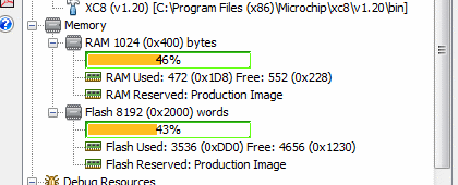
If you build this, you will notice that it uses 472 bytes (46%) of RAM and 3536 bytes (43%) of Flash. This still leaves a reasonable amount of space to actually do something useful.
The code I have put in is in ProcessIO, and just checks if we receive the characters ‘1’, ‘2’, ‘3’ or ‘4’. It will then change the speed at which the LED flashes, and return “Done” via the serial connection. You will replace this with something else, so I have made no attempt to make this code useful or well written.
In order to communicate with the PIC you will need a serial communication application on your PC. I have used Realterm, but any similar program should work.
Firmware for USB HID ?